Extending ICOM IC-E91 HT Frequency Range
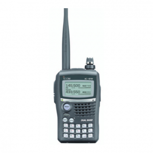
Description: Type: Amateur VHF/UHF transceiver
Frequency range: TX: 144-146 / 430-440 MHz
RX: 0.495-999.990 MHz
5/6.25/8.33/9/10/12.5/15/20/25/30/50/100/200 KHz steps
Mode: TX: FM (DV option (Digital voice) UT-121)
RX: AM/FM/WFM (DV option (Digital voice) UT-121)
RF Power output: Hi: 5/5
Lo: 0.5/0.5 W
Sensitivity: N/A
Selectivity: N/A
Image rejection: N/A
Voltage: ? VDC battery or 10-16 VDC external
Current drain: RX: 17-370 mA
TX: Max 2.2 A
Impedance: 50 ohms, SMA
Dimensions (W*H*D): 58*103*34 mm
Weight: 300 gr (with battery and antenna)
Manufactured: Japan, 2006-200x
Other: 1304 memories. DTMF and CTCSS. Spectrum scope
PC-programmable. Alpha tags. Twin RX. D-Star option
————————————————————————————————
Gentleman,
as u can see here, the default tx frequency range for icom ic-91 is only between 144-146 and 430-440 MHz
for those who want to extend their tx frequency range Allows TX from 137.000 – 174.000 and 400.000 – 470.000, just follow these simple steps.———————————————————————————-
Begin
———————————————————————————
Begin
———————————————————————————
1. Remove battery, and four screws inside the battery compartment.
2. Remove the two screws at the top (outside) back of the radio.
3. Pull front and back of radio apart gently. There will be a white flat ribbon cable connecting the two.
2. Remove the two screws at the top (outside) back of the radio.
3. Pull front and back of radio apart gently. There will be a white flat ribbon cable connecting the two.
4. (Optional) Pull the brown part of the ribbon cable connector upwards using your fingernail or small screwdriver. This will release the ribbon cable, and give your fingers some room to move the soldering iron.
5. Locate the diode D13. It is in the upper right hand corner. This diode needs to be removed for expanded TX operation. With a small tipped soldering iron, gently pull up on the diode as you melt the solder. You should be able to lift one side of the diode, then when you move the soldering iron to the other side, it should lift off (or fly across the table, never to be seen again).
6. Put the radio back together in the reverse order it was taken apart.
7. DONE! now u can test your handy talkie.
This modification does allow the DV mode to be used on any TX band.



2 comments