SSB – Single sideband modulation
a summary, information or overview describing what is SSB modulation, and how single sideband modulation works as well as details of SSB receiver, SSB, transmitter, and SSB transceiver circuits and how it is used for two way radio communication.
Single sideband modulation is widely used in the HF portion, or short wave portion of the radio spectrum for two way radio communication. There are many users of single sideband modulation. Many users requiring two way radio communication will use single sideband and they range from marine applications, generally HF point to point transmissions, military as well as radio amateurs or radio hams.
Single sideband modulation or SSB is derived from amplitude modulation (AM) and SSB modulation overcomes a number of the disadvantages of AM.
Single sideband modulation is normally used for voice transmission, but technically it can be used for many other applications where two way radio communication using analogue signals is required.
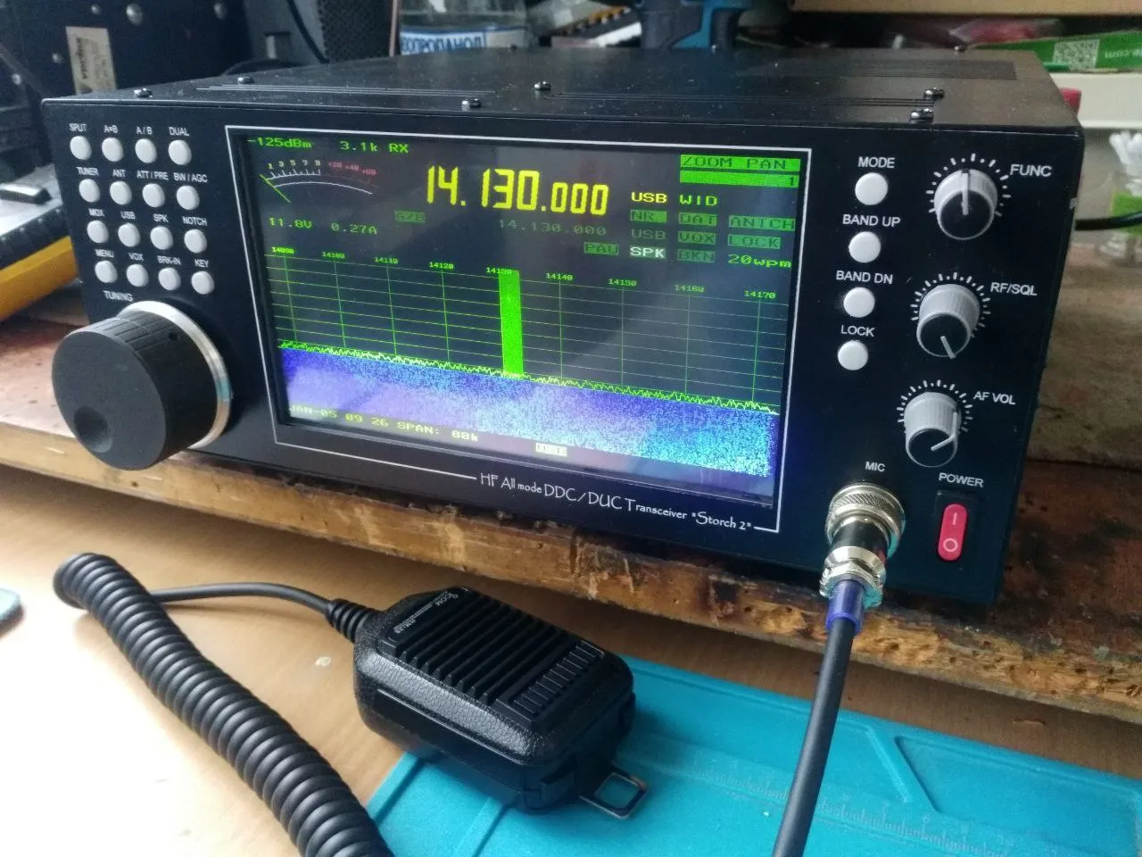
As a result of its widespread use there are many items of radio communication equipment designed to use single sideband radio including: SSB receiver, SSB transmitter and SSB transceiver equipments.
What is single sideband modulation?
Single sideband, SSB modulation is basically a derivative of amplitude modulation, AM. By removing some of the components of the ordinary AM signal it is possible to significantly improve its efficiency.
A more complete explanation of the way amplitude modulated signals are formed and work can been seen on the pages relating to AM. These can be accessed via the “Related Articles” links that can be found on the left hand side of the page below the main menu.
It is possible to see how an AM signal can be improved by looking at the spectrum of the signal. When a steady state carrier is modulated with an audio signal, for example a tone of 1 kHz, then two smaller signals are seen at frequencies 1 kHz above and below the main carrier.
If the steady state tones are replaced with audio like that encountered with speech of music, these comprise many different frequencies and an audio spectrum with frequencies over a band of frequencies is seen. When modulated onto the carrier, these spectra are seen above and below the carrier.
It can be seen that if the top frequency that is modulated onto the carrier is 6 kHz, then the top spectra will extend to 6 kHz above and below the signal. In other words the bandwidth occupied by the AM signal is twice the maximum frequency of the signal that is used to modulated the carrier, i.e. it is twice the bandwidth of the audio signal to be carried.
Amplitude modulation is very inefficient from two points. The first is that it occupies twice the bandwidth of the maximum audio frequency, and the second is that it is inefficient in terms of the power used. The carrier is a steady state signal and in itself carries no information, only providing a reference for the demodulation process. Single sideband modulation improves the efficiency of the transmission by removing some unnecessary elements. In the first instance, the carrier is removed – it can be re-introduced in the receiver, and secondly one sideband is removed – both sidebands are mirror images of one another and the carry the same information. This leaves only one sideband – hence the name Single SideBand / SSB.
SSB receiver
While signals that use single sideband modulation are more efficient for two way radio communication and more effective than ordinary AM, they do require an increased level of complexity in the receiver. As SSB modulation has the carrier removed, this needs to be re-introduced in the receiver to be able to reconstitute the original audio. This is achieved using an internal oscillator called a Beat Frequency Oscillator (BFO) or Carrier Insertion Oscillator (CIO). This generates a carrier signal that can be mixed with the incoming SSB signal, thereby enabling the required audio to be recovered in the detector.
Typically the SSB detector itself uses a mixer circuit to combine the SSB modulation and the BFO signals. This circuit is often called a product detector because (like any RF mixer) the output is the product of the two inputs.
It is necessary to introduce the carrier using the BFO / CIO on the same frequency relative to the SSB signal as the original carrier. Any deviation from this will cause the pitch of the recovered audio to change. Whilst errors of up to about 100 Hz are acceptable for communications applications including amateur radio, if music is to be transmitted the carrier must be reintroduced on exactly the correct frequency. This can be accomplished by transmitting a small amount of carrier, and using circuitry in the receiver to lock onto this.
Receiving SSB
There are several types of two way radio communication that it is possible to listen to legally. Radio amateurs form a large group that short wave listeners can listen to quite legally, and the transmissions are easy to find as they are all contained within the amateur radio band allocations – see the section of this website on ham radio.
In view of its popularity it is necessary to know how to tune an SSB signal and receive the SSB signal in the best way to ensure that the best copy is obtained. Although it is slightly more difficult to tune than an AM or FM signal, with a little practice, it is easy to become used to tuning them in.
When receiving SSB it is necessary to have a basic understanding of how a receiver works. Most radio receivers that will be used to receive SSB modulation will be of the superheterodyne type. Here the incoming signals are converted down to a fixed intermediate frequency. It is at this stage where the BFO signal is mixed with the incoming SSB signals.
It is necessary to set the BFO to the correct frequency to receive the form of SSB, either LSB or USB, that is expected. Many radio receivers will have a switch to select this, other receivers will have a BFO pitch control which effectively controls the frequency. The BFO needs to be positioned to be in the correct position for when the signal is in the centre of the receiver passband. This typically means that it will be on the side of the passband of the receiver. To position the BFO, tune the SSB signal in for the optimum strength, i.e. ensure it is in the centre of the passband, and then adjust the BFO frequency for the correct pitch of the signal. Once this has been done, then the main tuning control of the receiver can be used, and once a signal is audible with the correct pitch, then it is also in the centre of the receiver passband.
Tuning an SSB signal with the BFO set is quite easy. First set the receiver to the SSB position or the BFO to ON, and then if there is a separate switch set the LSB / USB switch to the format that is expected and then gradually tune the receiver. Adjust the main tuning control so that the pitch is correct, and the signal should be comprehensible. If it is not possible to distinguish the sounds, then set the LSB / USB switch to the other position and re-adjust the main tuning control if necessary to return the signal to the correct pitch, at which point the signal should be understandable..
With a little practice it should be possible to easily tune in SSB signals.
Single sideband power measurement
It is often necessary to define the output power of a single sideband transmitter or single sideband transmission. For example it is necessary to know the power of a transmitter sued for two way radio communication to enable its effectiveness to be judged for particular applications.
Power measurement for an SSB signal is not as easy as it is for many other types of transmission because the actual output power is dependent upon the level of the modulating signal. To overcome this a measure known as the peak envelope power (PEP) is used. This takes the power of the RF envelope of the transmission and uses the peak level of the signal at any instant and it includes any components that may be present. Obviously this includes the sideband being used, but it also includes any residual carrier that may be transmitted.
The level of the peak envelope power may be stated in Watts, or nowadays figures quoted in dBW or dBm may be used. These are simply the power levels relative to 1 Watt or 1 milliwatt respectively. As an example a signal of 10 watts peak envelope power is 10 dB above a 1 Watt signal and therefore it has a power of 10 dBW. Similar logic can be used to determine powers in dBm.
Single sideband modulation variants
There are many variants of single sideband modulation that are used, and there are several different abbreviations for them. These are explained below.
LSB: This stands for Lower Sideband. This form of single sideband modulation is formed when the lower sideband only of the original signal is transmitted. Typically this is used by radio amateurs or radio hams on their allocations below 9 MHz.
USB: This stands for Upper Sideband. This form of single sideband modulation is formed when the upper sideband only of the original signal is transmitted. Typically this form of SSB modulation is used by professional users on all frequencies and by radio amateurs or radio hams on their allocations above 9 MHz.
DSB: This is Double Sideband and it is a form of modulation where an AM signal is taken and the carrier is removed to leave the two sidebands. Although easy to generate, it does not give any improvements in spectrum efficiency and it is also not particularly easy to resolve. Accordingly it is rarely used.
SSB SC: This stands for Single Sideband Suppressed Carrier. It is the form of SSB modulation where the carrier is removed completely as opposed to SSB reduced carrier where some of the carrier is left.
VSB: This stands for Vestigial Sideband. It is a form is signal where one sideband is completely present, and the other sideband that has been only partly cut off or suppressed. It is widely used for analogue television transmissions. It comes in useful because the baseband video signal is wide (typically 6 MHz). To transmit this using AM would require a bandwidth of 12 MHz. To reduce the amount of spectrum used, one sideband is transmitted fully, whereas only the lower frequencies of the other are transmitted. The high frequencies can be later enhanced using filters.
SSB reduced carrier : In this form of SSB modulation one sideband is present along with a small amount of the carrier. For some applications, a small amount of carrier is kept. This may be used to provide a reference signal for accurate demodulation.
SSB advantages
Single sideband modulation is often compared to AM, of which it is a derivative. It has several advantages for two way radio communication that more than outweigh the additional complexity required in the SSB receiver and SSB transmitter required for its reception and transmission.
As the carrier is not transmitted, this enables a 50% reduction in transmitter power level for the same level of information carrying signal. [NB for an AM transmission using 100% modulation, half of the power is used in the carrier and a total of half the power in the two sideband – each sideband has a quarter of the power.]
As only one sideband is transmitted there is a further reduction in transmitter power.
As only one sideband is transmitted the receiver bandwidth can be reduced by half. This improves the signal to noise ratio by a factor of two, i.e. 3 dB, because the narrower bandwidth used will allow through less noise and interference.
The summary of this is that SSB modulation offers a far more effective solution for two way radio communication because it provides a significant improvement in efficiency.
Summary
Single sideband modulation, SSB is the main modulation format used for analogue voice transmission for two way radio communication on the HF portion of the radio spectrum. Its efficiency in terms of spectrum and power when compared to other modes means that for many years it has been the most effective option to use. Now some forms of digital voice transmission are being used, but it is unlikely that single sideband will be ousted for many years as the main format used on these bands.




Post Comment