Electrical Insulation Testing vs Electrical Resistance Testing: What’s the Difference?
Both electrical insulation testing and electrical resistance testing are crucial methods used in maintaining the safety and reliability of electrical systems. While they may sound similar, they serve different purposes and are used to measure different aspects of an electrical system’s performance. Below is an explanation of each method, step-by-step instructions on how to perform them, and common test devices to use.
What is Electrical Insulation Testing?
Electrical insulation testing refers to the process of assessing the quality and integrity of the insulation material that surrounds electrical conductors. Insulation in electrical systems is critical because it prevents unintended contact between live conductors and grounded surfaces, reducing the risk of electrical shocks, short circuits, and fires.
Purpose of Electrical Insulation Testing:
- Verify Insulation Integrity: Insulation testing determines whether the insulation surrounding electrical wires, cables, or equipment is intact and functioning properly. It ensures there are no breakdowns, cracks, or moisture ingress that might allow electrical leakage.
- Prevent Failures: If insulation deteriorates, it can lead to unsafe conditions such as electrical shocks or equipment damage. Testing ensures that insulation materials maintain their protective properties over time.
- Ensure Compliance: Electrical insulation testing is required by safety standards for certain electrical installations and equipment, ensuring compliance with regulatory guidelines.
Step-by-Step: How to Perform Electrical Insulation Testing
- Turn Off Power: Ensure that the system is powered off before performing the test. This minimizes the risk of electrical shocks and interference during the testing process.
- Select the Right Test Voltage: Choose the correct test voltage according to the equipment being tested:
- 500V for low-voltage systems (e.g., household wiring).
- 1000V or higher for larger equipment (e.g., transformers, motors).
- Connect the Megger:
- Attach one test lead to the conductor or terminal of the equipment you’re testing.
- Attach the other test lead to the ground or earth terminal (or the outer sheath of the cable if testing a wire).
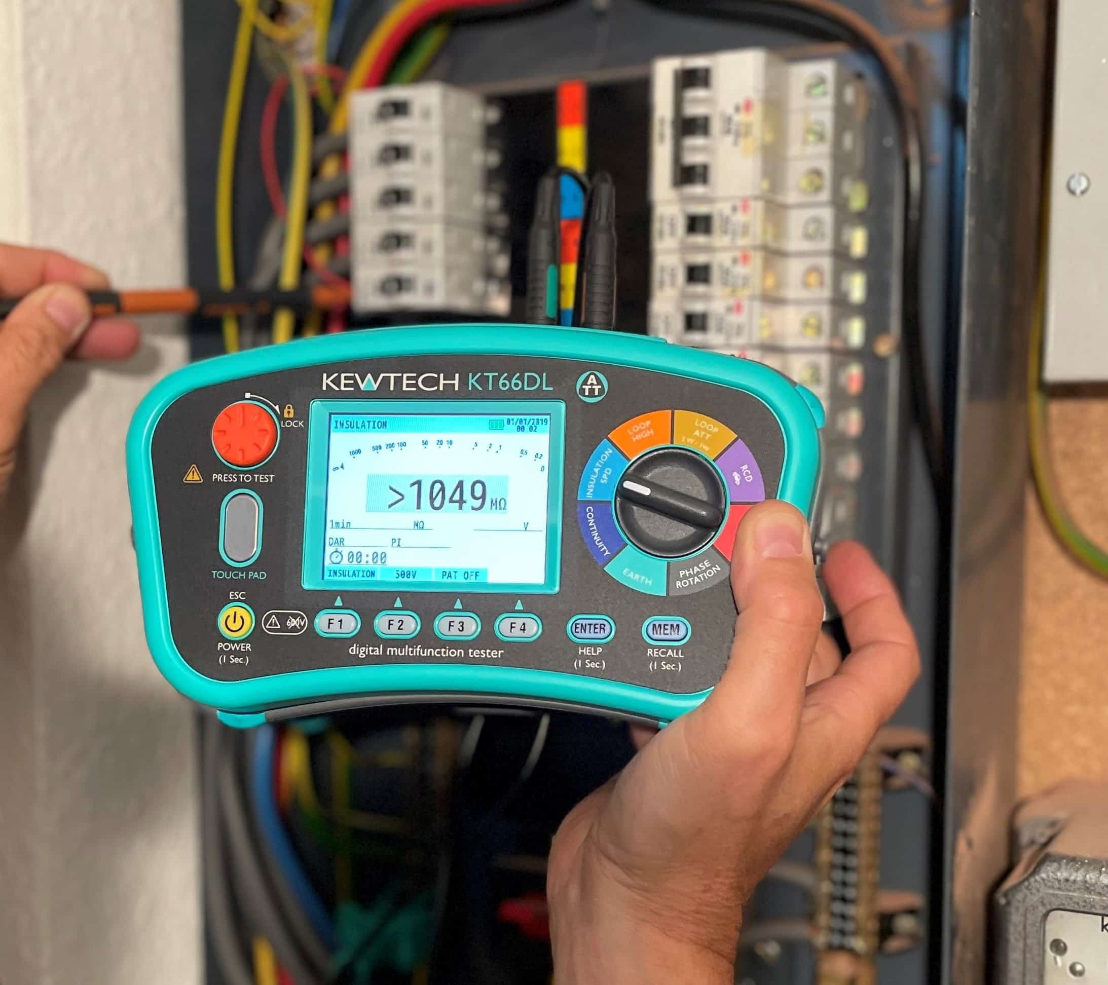
- Start the Test: Turn on the insulation tester (Megger) and apply the test voltage. The tester will generate a high-voltage DC signal to check the integrity of the insulation.
- Monitor the Test Results:
- Good Insulation: The test will show high resistance, typically above 1 MΩ.
- Faulty Insulation: A lower resistance reading, approaching 0 MΩ, indicates a problem with the insulation.
- Interpret the Results: If the resistance is within acceptable limits (typically 1 MΩ or higher), the insulation is deemed safe. If the reading is low, corrective actions such as replacing the cables or insulation are required.
- Disconnect the Test Leads: Once the test is complete, remove the test leads and restore the system’s power.
Common Devices Used for Electrical Insulation Testing:
- Megger: A leading brand for insulation resistance testing. Example models include the MIT400 Series and IR4055.
- Fluke Insulation Testers: Known for their accuracy and reliability. Models like the Fluke 1507 are widely used.
- Chauvin Arnoux C.A. 6500: A versatile insulation tester suitable for a variety of industrial and commercial applications.
What is Electrical Resistance Testing?
Electrical resistance testing refers to measuring the resistance in an electrical conductor or circuit. This type of testing ensures that electrical connections are working efficiently and that there are no faults, such as corrosion or loose connections, that could affect conductivity.
Purpose of Electrical Resistance Testing:
- Check for High Resistance: It ensures that there is minimal opposition to current flow. High resistance in conductors leads to inefficiencies, heating, and power loss.
- Verify Continuity: It checks for continuity in electrical circuits, ensuring no open circuits or broken connections that could lead to system failure.
Step-by-Step: How to Perform Electrical Resistance Testing
- Power Off the System: As with insulation testing, make sure the system is powered down to ensure safety during the test.
- Select the Right Meter: Use an ohmmeter, multimeter, or a low-resistance ohmmeter (for precise measurements) to test the resistance in the circuit or conductor.
- Connect the Test Leads:
- Place one test lead on the positive terminal of the circuit (or the start of the conductor).
- Attach the second test lead to the negative terminal or the end of the conductor.
- Measure the Resistance: Turn on the meter and take a reading. A low resistance (close to 0 ohms) indicates a good connection, while high resistance suggests poor conductivity, which could be caused by corrosion, loose connections, or damaged components.
- Test Multiple Points: For larger systems, test at various points to identify where the resistance is higher and pinpoint potential issues like faulty connections.
- Interpret the Results: The lower the resistance value, the better the conductivity. A high resistance could point to a bad connection, damaged wire, or corrosion.
- Disconnect the Test Leads: After taking measurements, disconnect the test leads and restore the power to the system.
Common Devices Used for Electrical Resistance Testing:
- Fluke Multimeters: Known for versatile, high-quality tools suitable for resistance testing, such as the Fluke 87V.
- Klein Tools Multimeters: Affordable and reliable for DIY and professional use, including resistance measurement.
- Keysight Technologies Digital Multimeter: Offers high precision for resistance testing in complex systems.
Key Differences Between Insulation Testing and Resistance Testing
| Aspect | Electrical Insulation Testing | Electrical Resistance Testing |
|---|---|---|
| Purpose | Checks the integrity of insulation materials | Measures the resistance of conductors or components in a circuit |
| What Is Measured | Insulation resistance (Megaohms, MΩ) | Electrical resistance (Ohms, Ω) |
| Test Method | High-voltage DC signal applied to the insulation and ground | Low-voltage current is passed through the conductor or circuit |
| Test Device | Insulation resistance tester (e.g., Megger) | Multimeter, ohmmeter, or low-resistance ohmmeter |
| Application | Prevents electrical leakage, ensures safety, and detects insulation degradation | Ensures proper conductivity and checks for faults or inefficiencies |
| Typical Voltage Used | 250V to 5kV DC (depending on system) | Low voltage (usually 1-10V) |
| Primary Focus | Insulation health and safety | Conductivity and continuity of electrical current |
Conclusion
Both electrical insulation testing and electrical resistance testing are essential for maintaining the safety, efficiency, and reliability of electrical systems. Insulation testing primarily focuses on the protective barriers around conductors, while resistance testing ensures that electrical circuits are operating optimally with minimal power loss or faults.
Whether you’re an amateur radio enthusiast testing your station’s power supply or a professional working on industrial electrical systems, understanding the differences between these two tests and knowing when and how to perform them is key to maintaining a safe and functional electrical setup.
Have you used a Megger or a resistance tester in your electrical projects? Share your experiences or ask any questions in the comments below!


Post Comment