amateur radio
earthing
electrical
grounding
ham radio
test
#EarthElectrodeResistance, #Earthing, #EarthResistanceTester, #ElectricalCompliance, #ElectricalEngineering, #ElectricalGrounding, #ElectricalHazards, #ElectricalInstallation, #ElectricalMaintenance, #ElectricalSafety, #ElectricalStandards, #ElectricalTesting, #GroundingElectrode, #groundingsystem, #SafetyFirst
9M2PJU
0 Comments
Understanding Earth Electrode Resistance Testing: A Comprehensive Guide
When it comes to electrical installations, safety is paramount. One of the critical aspects of ensuring electrical safety is the proper grounding of electrical systems. Grounding, or earthing, provides a safe path for electrical currents to flow into the earth, preventing electric shocks, fires, and equipment damage. To ensure that the grounding system is effective, it is essential to conduct an Earth Electrode Resistance Test. This blog post will delve into the purpose, methodology, and importance of this test, providing a detailed guide for both professionals and enthusiasts.
What is an Earth Electrode Resistance Test?
An Earth Electrode Resistance Test is a procedure used to measure the resistance of an earth electrode to the surrounding soil. The test ensures that the electrode is properly installed and provides a low-resistance path for fault currents to dissipate into the ground. The test is crucial for verifying the effectiveness of the grounding system, which is vital for the safety and reliability of electrical installations.
Objectives of the Test
The primary objectives of conducting an Earth Electrode Resistance Test are:
- Ensure Proper Placement of Electrodes: The test ensures that the electrode is not placed in an area where its resistance overlaps with other electrodes, which could compromise the effectiveness of the grounding system.
- Verify Suitability of Electrode Position: The test helps determine whether the electrode is installed in a suitable location, ensuring optimal performance.
- Measure Earth Electrode Resistance: The test measures the resistance of the earth electrode, ensuring it meets the required standards for safe electrical operation.
Equipment Used for the Test
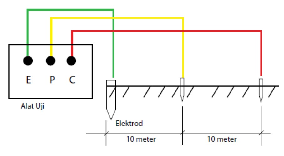
The primary tool used for this test is the Earth Resistance Tester. This device is designed to measure the resistance between the earth electrode and the surrounding soil. The tester typically has three terminals:
- Terminal E: Connected to the earth electrode under test (green conductor).
- Terminal P: Connected to the potential spike (yellow conductor), placed at a specific distance from the electrode.
- Terminal C: Connected to the current spike (red conductor), placed at a further distance from the electrode.
Step-by-Step Testing Procedure
The Earth Electrode Resistance Test involves a series of steps to ensure accurate and reliable measurements. Here’s a detailed breakdown of the process:
Step 1: Connect the Earth Resistance Tester
- Connect Terminal E: Attach Terminal E of the Earth Resistance Tester to the earth electrode you wish to test. This is typically done using a green conductor.
- Connect Terminal P: Place the potential spike (yellow conductor) at a distance of 10 meters from the earth electrode and connect it to Terminal P.
- Connect Terminal C: Place the current spike (red conductor) at a distance of 20 meters from the earth electrode and connect it to Terminal C.
Step 2: Conduct the Initial Measurement
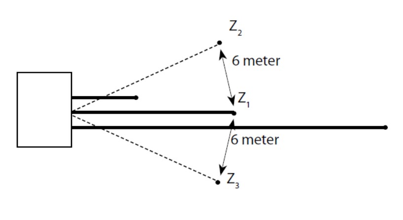
First Reading (Z1): Record the first reading from the Earth Resistance Tester. For example, Z1 = 10 Ω.
Step 3: Reposition the Potential Spike
Second Reading (Z2): Move the potential spike 6 meters from its original position and record the second reading. For example, Z2 = 10 Ω.

Step 4: Reposition the Potential Spike Again
Third Reading (Z3): Move the potential spike another 6 meters from its previous position and record the third reading. For example, Z3 = 10 Ω.
Step 5: Calculate the Average Resistance
Step 5: Calculate the Average Resistance
To determine the average resistance, use the three recorded values (Z1, Z2, and Z3) from the Earth Electrode Resistance Test. The formula for calculating the average resistance (Z_avg) is:
Z_avg = (Z1 + Z2 + Z3) / 3
For example, if the three recorded values are Z1 = 10 Ω, Z2 = 10 Ω, and Z3 = 10 Ω, the calculation would be:
Z_avg = (10 + 10 + 10) / 3 = 10 Ω
The average resistance value (Z_avg) is used to evaluate the effectiveness of the earth electrode. A lower average resistance indicates a more efficient grounding system, while a higher value may suggest the need for corrective measures. This step ensures accurate and reliable results by accounting for any variations in the measurements.
Importance of Repeating the Test
The test is repeated at least three times to ensure accuracy. Repositioning the potential spike helps to avoid overlapping resistance zones, which could lead to inaccurate readings. By taking multiple measurements and calculating the average, you can obtain a more reliable value for the earth electrode resistance.
Interpreting the Results
The average resistance value obtained from the test should be compared against the acceptable standards for earth electrode resistance. Generally, a lower resistance value indicates a more effective grounding system. The acceptable resistance value may vary depending on local regulations and the specific requirements of the electrical installation.
- Low Resistance (e.g., 10 Ω or less): Indicates a well-installed and effective grounding system.
- High Resistance (e.g., above 10 Ω): Suggests potential issues with the grounding system, such as poor soil conductivity or improper installation of the electrode.
If the resistance value is too high, further investigation and corrective actions may be necessary, such as improving the soil conductivity, using additional electrodes, or repositioning the existing electrode.
Conclusion
The Earth Electrode Resistance Test is a vital procedure for ensuring the safety and effectiveness of electrical grounding systems. By following the outlined steps and using the appropriate equipment, you can accurately measure the resistance of an earth electrode and verify its suitability for protecting electrical installations. Regular testing and maintenance of grounding systems are essential to prevent electrical hazards and ensure the reliable operation of electrical equipment.
Whether you’re a professional electrician or a DIY enthusiast, understanding and conducting an Earth Electrode Resistance Test is a valuable skill that contributes to the overall safety and efficiency of electrical systems. Always adhere to local electrical codes and standards, and consult with a qualified professional if you encounter any issues during the testing process.
By ensuring that your grounding system is up to par, you can protect both people and property from the dangers of electrical faults, making the world a safer place, one earth electrode at a time.


Post Comment