amateur radio
earthing
electrical
grounding
ham radio
test
#EarthingSystem, #EarthLoopImpedance, #ElectricalCompliance, #ElectricalEngineering, #ElectricalHazards, #ElectricalInspection, #ElectricalInstallation, #ElectricalMaintenance, #ElectricalPrevention, #ElectricalSafety, #ElectricalStandards, #ElectricalTesting, #ProtectiveDevices, #SafetyFirst
9M2PJU
0 Comments
Understanding Electrical Earth Loop Impedance Testing: A Comprehensive Guide
Electrical safety is a cornerstone of any well-designed electrical installation. One of the critical tests to ensure this safety is the Earth Loop Impedance Test. This test measures the impedance of the earth fault loop, which is essential for determining the effectiveness of the earthing system and ensuring that protective devices, such as circuit breakers and fuses, operate correctly during a fault. In this blog post, we will delve into the purpose, methodology, and technical details of Earth Loop Impedance Testing, providing a detailed guide for professionals and enthusiasts alike.
What is Earth Loop Impedance Testing?
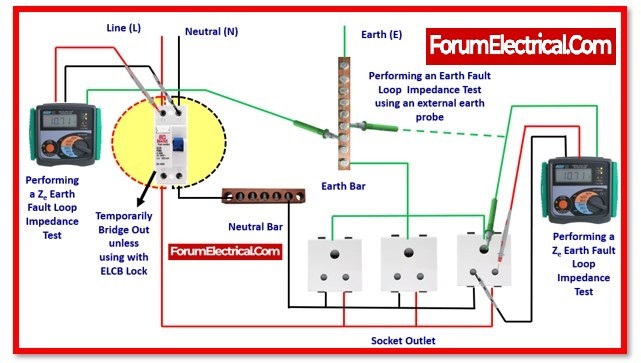
Earth Loop Impedance Testing is a procedure used to measure the impedance of the earth fault loop in an electrical installation. The earth fault loop is the path that fault current takes when a live conductor comes into contact with an earthed part of the system. The test ensures that the impedance is low enough to allow sufficient fault current to flow, enabling protective devices to operate within the required time.
Objectives of the Test
The primary objectives of conducting an Earth Loop Impedance Test are:
- Determine Earth Loop Impedance: Measure the impedance of the earth fault loop to ensure it is within acceptable limits.
- Verify Protective Device Operation: Ensure that protective devices, such as circuit breakers and fuses, will operate correctly during a fault.
- Select Appropriate Earth Leakage Protection: Determine the type of earth leakage protection suitable for the installation.
Types of Earth Loop Impedance Tests
There are two main types of Earth Loop Impedance Tests:
- Line-to-Earth Loop Test: Measures the impedance between the line conductor and the earth.
- Neutral-to-Earth Loop Test: Measures the impedance between the neutral conductor and the earth.
Both tests are essential for ensuring the safety and reliability of the electrical installation.
Equipment Used for the Test
The primary tool used for this test is the Earth Loop Impedance Tester. This device applies a small test current to the earth fault loop and measures the impedance. The tester typically has the following features:
- Test Buttons: For initiating the test.
- Probes and Clips: For connecting to the line, neutral, and earth conductors.
- Display: For showing the measured impedance value.
Step-by-Step Testing Procedure
The Earth Loop Impedance Test involves a series of steps to ensure accurate and reliable measurements. Here’s a detailed breakdown of the process:
Step 1: Prepare the Circuit for Testing
- Turn Off the Main Supply: Ensure the main circuit breaker is in the “off” position to disconnect the power supply.
- Verify Main Protective Bonding: Ensure all main protective bonding conductors are connected to the main earthing terminal. This ensures that fault currents can safely dissipate.
- Disconnect the Earth Conductor: Temporarily disconnect the earth conductor from the main earthing terminal.
Step 2: Connect the Earth Loop Impedance Tester
- Connect the Earth Clip: Attach the earth clip of the tester to the disconnected earth conductor.
- Connect the Line Probe: Connect the line probe of the tester to the line terminal of the main supply switch.
Step 3: Perform the Test
- Initiate the Test: Press the ‘Test’ button on the Earth Loop Impedance Tester to apply the test current and measure the impedance.
- Record the Reading: Note the impedance value displayed on the tester.
Step 4: Repeat for Three-Phase Installations
- Test Each Line Conductor: For three-phase installations, repeat the test for each line conductor (L1, L2, L3).
- Record External Earth Loop Impedance (Ze): The highest recorded value is taken as the external earth loop impedance (Ze).
Step 5: Reconnect the Earth Conductor
- Reconnect the Earth Conductor: After completing the test, reconnect the earth conductor to the main earthing terminal.
Technical Considerations and Interpretation of Results
Importance of Low Impedance
A low earth loop impedance is crucial for the effective operation of protective devices. The impedance must be low enough to allow sufficient fault current to flow, ensuring that the protective device operates within the required time. High impedance can result in delayed operation or failure of the protective device, leading to dangerous situations.
Acceptable Impedance Values
The acceptable impedance values depend on the type of protective device and the installation’s characteristics. For example:
- Circuit Breakers: The impedance must be low enough to ensure the breaker trips within the specified time (e.g., 0.4 seconds for final circuits in domestic installations).
- Fuses: The impedance must allow the fuse to blow quickly during a fault.
Refer to local electrical standards and regulations for specific impedance limits.
Factors Affecting Earth Loop Impedance
Several factors can affect the earth loop impedance, including:
- Conductor Size and Length: Larger conductors and shorter lengths result in lower impedance.
- Soil Resistivity: High soil resistivity can increase the impedance of the earth electrode.
- Connection Quality: Poor connections can increase impedance and reduce the effectiveness of the earthing system.
Importance of Earth Loop Impedance Testing
- Ensures Safety: The test verifies that the earthing system can safely dissipate fault currents, preventing electric shocks and fires.
- Compliance with Standards: The test ensures the installation complies with safety standards and regulations.
- Verifies Protective Device Operation: The test confirms that protective devices will operate correctly during a fault.
- Identifies Faults: The test can identify issues such as high impedance, poor connections, or inadequate earthing.
Common Testing Locations
The Earth Loop Impedance Test is conducted at various locations in an electrical installation, including:
- Main Distribution Board: To measure the external earth loop impedance (Ze).
- Final Circuits: To measure the earth loop impedance at the furthest point of each circuit (Zs).
Key Considerations During Testing
- Safety First: Always ensure the circuit is de-energized before starting the test. Use appropriate personal protective equipment (PPE) and follow safety protocols.
- Accurate Connections: Ensure all connections are secure and clean to avoid inaccurate readings.
- Environmental Factors: Temperature and humidity can affect the test results. Conduct the test under suitable conditions.
Conclusion
Earth Loop Impedance Testing is a vital procedure for ensuring the safety, reliability, and compliance of electrical installations. By following the outlined steps and using the appropriate equipment, you can effectively measure the earth loop impedance and verify the effectiveness of the earthing system. Regular testing and maintenance of electrical systems are essential to prevent accidents, protect equipment, and ensure the efficient operation of electrical installations.
Whether you’re a professional electrician or a DIY enthusiast, understanding and conducting Earth Loop Impedance Testing is a valuable skill that contributes to the overall safety and efficiency of electrical systems. Always adhere to local electrical codes and standards, and consult with a qualified professional if you encounter any issues during the testing process.
By prioritizing electrical safety, we can create a safer environment for everyone, one circuit at a time.


Post Comment