amateur radio
antenna
antenna calculation
antenna design
calculator
ham radio
quad antenna calculator
amateur radio, antenna bandwidth, antenna calculations, antenna construction, antenna design, antenna engineering, antenna gain, antenna history, antenna performance, antenna technology, antenna theory, antenna tuning, directional antenna, driven element, DX performance, ham radio, HF antenna, high-altitude antenna, impedance matching, loop antenna, multi-band antenna, parasitic elements, quad antenna, radio antenna, Radio communication, radio hobby, radio waves, VHF antenna, yagi antenna
9M2PJU
0 Comments
The History and Design of the Quad Antenna
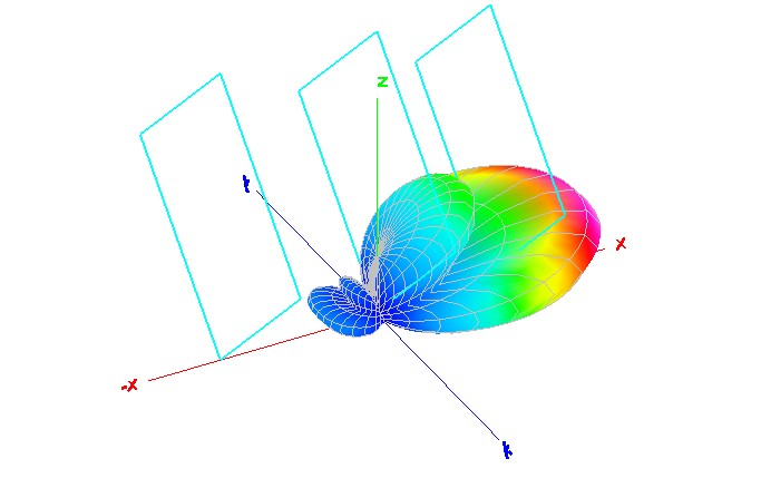
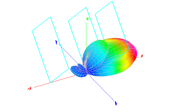
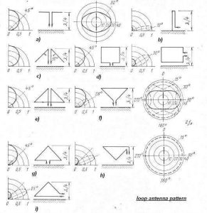
A quad antenna is a type of directional wire radio antenna that is widely used in HF and VHF bands. Unlike the Yagi–Uda antenna, which utilizes dipole elements, the quad antenna consists of loop elements that may be square, circular, or other shapes. This design offers several advantages, including reduced interference from coronal discharge, higher impedance, and improved gain.
The Origins of the Quad Antenna
The quad antenna has its roots in several historical inventions and patents:
- 1924 – Moses Jacobson patented a loop antenna with a rhombic shape.
- 1938 – George Brown and others patented a rhombic loop antenna with quarter-wave sides.
- 1951 – Clarence C. Moore (W9LZX), an engineer at HCJB, a high-altitude shortwave missionary station in Ecuador, developed and patented the modern quad antenna. His design aimed to mitigate issues related to coronal discharges at high altitudes.
- 1957 – James Sherriff McCaig patented the cubical multi-band quad antenna.
- 1960s-1970s – Various improvements were made, including the Swiss quad, DJ4VM quad, and the Mono-loop tri-band cubical quad.
Moore’s work led to the first practical use of a quad antenna, eliminating end effects that cause corona discharge in traditional Yagi antennas. His loop-based design also provided higher gain and improved impedance characteristics, making it an efficient alternative to dipole-based Yagi antennas.
Quad Antenna Design and Calculations
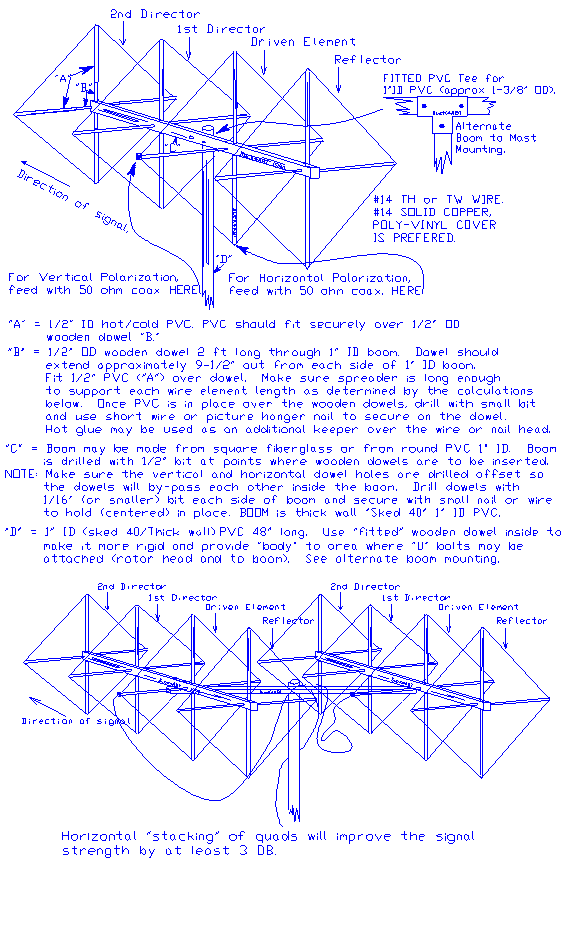
The quad antenna consists of at least two main elements:
- Driven Element: A full-wave loop that serves as the radiating part of the antenna.
- Parasitic Elements: Reflectors and directors that enhance the antenna’s directionality and gain.
The basic formula for calculating the element length in a quad antenna is:
L = 1005 / f
Where:
- L = Total length of the loop (in feet)
- f = Frequency of operation (in MHz)
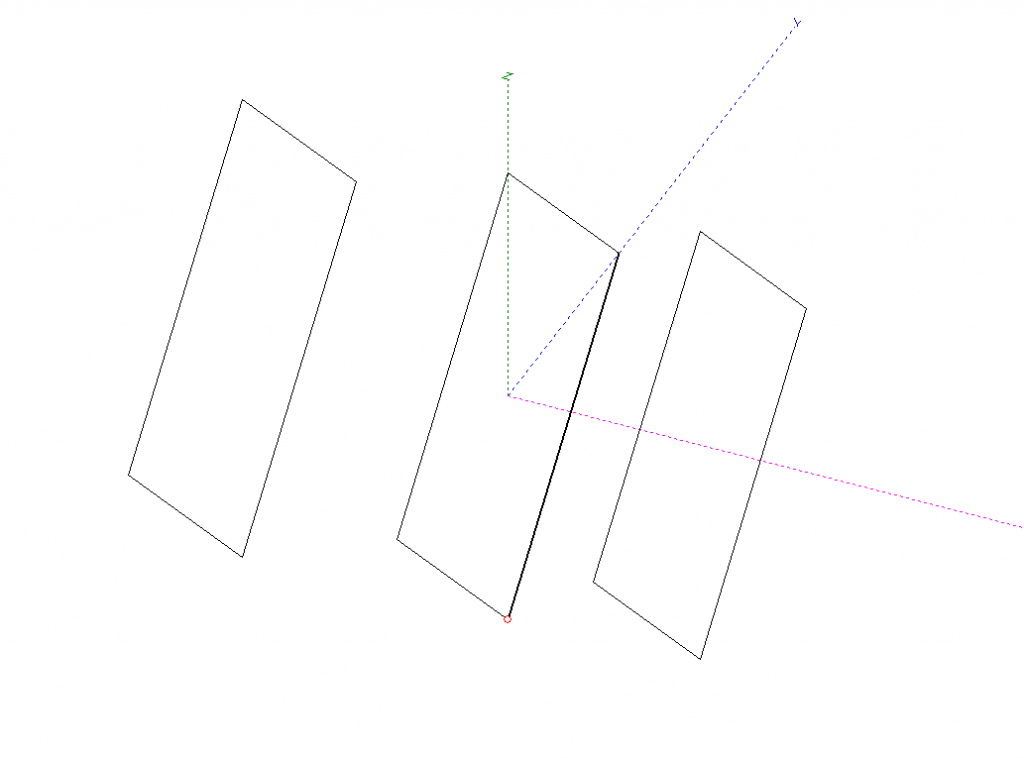
For a square quad loop, each side length is given by:
S = L / 4
Where:
- S = Side length of the square loop (in feet)
- L = Total length of the loop (in feet)
For optimal performance, the spacing between the elements (reflector, driven element, and director) is typically between 0.15 to 0.2 wavelengths.
Advantages of Quad Antennas
Compared to traditional Yagi antennas, quads offer several benefits:
- Higher Gain: A 2-element quad can provide a gain equivalent to a 3-element Yagi, while a 3-element quad offers even more.
- Multi-band Capability: Quads can be designed for multiple bands with minimal interaction between elements.
- Lower Radiation Angle: This leads to improved DX performance.
- Lower SWR and Impedance Matching: The higher impedance of quads makes them easier to match with 50-ohm coaxial feeds.
Disadvantages of Quad Antennas
Despite their benefits, quad antennas also have some drawbacks:
- Complex Construction: Unlike Yagis, quads require a rigid frame to support the wire loops.
- Wind Resistance: Larger quads can be affected by strong winds, requiring robust support structures.
- Limited Bandwidth: Tuning for maximum gain results in a narrower bandwidth.
Conclusion
The quad antenna remains a popular choice among radio amateurs due to its high efficiency and superior performance over Yagi antennas in certain conditions. While construction is more complex, the improved gain, impedance characteristics, and reduced interference make it an excellent option for HF and VHF applications.
References
- Clarence C. Moore, “Loop Antenna Design for High-Altitude Transmission,” Patent No. 2,537,191 (1951).
- Wm. Orr, “The Quad Antenna Handbook,” (1996).
- Jefferies & Koulouris, “Dielectric Effects on Loop Antennas,” IEEE Antennas and Propagation, (2003).
Visit https://www.wireantennas.co.uk/quad-antenna-calculator


Post Comment