9M2PJU
9m2pju, amateuradio, antenna, balance, balanced line, characteristicimpedance, conductor, contesting, dipole, DXCluster, dxing, feeder, hamradio, hamradiodx, HF, hfconditions, ionosphere, ladder line, ladderline, propagation, QRZ, RadioFrequency, radiooperator, RadioWaves, rfengineering, transmission line, transmissionline, twinlead, VHF, vhfconditions
9M2PJU
0 Comments
Understanding Parallel Circular Conductor Transmission Line Calculations
Transmission lines play a crucial role in radio communications, ensuring efficient signal transfer between antennas and radio equipment. One common type of transmission line used by amateur radio operators is the parallel circular conductor transmission line. This type of line includes ladder lines, twin-lead cables, and open-wire feed lines, which are widely used for high-impedance antenna systems such as the G5RV.
What is a Parallel Circular Conductor Transmission Line?
A parallel circular conductor transmission line consists of two cylindrical conductors running parallel to each other, separated by an insulating medium (typically air or another dielectric). The key parameter that defines the transmission line’s behavior is its characteristic impedance (Zc), which depends on the conductor diameter (d), the spacing between them (s), and the dielectric constant of the medium (εr).
Practical Applications
Understanding these calculations is essential for designing and constructing transmission lines with a specific impedance. For example:
- Twin-lead cables (typically 300Ω) are commonly used for television antennas.
- Ladder lines (often 450Ω) are used in amateur radio for multi-band antenna systems, especially when impedance matching is needed.
- Open-wire lines (typically 600Ω) are preferred for high-efficiency HF antenna feeding.
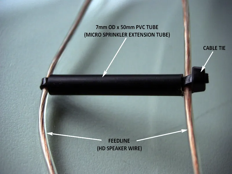
Building a Ladder Line
Leon Salden, VK3VGA, has shared an innovative way to construct a ladder line spreader using a black polyethylene irrigation tube and cable ties. This method ensures durability and proper conductor spacing, helping maintain the desired impedance.
Using the Transmission Line Calculator
For those who want an easy way to calculate transmission line dimensions, a Parallel Circular Conductor Transmission Line Calculator is available online. This tool simplifies the process, allowing users to input their desired impedance and conductor diameter to obtain spacing values instantly.
For more details and to use the calculator, visit Parallel Circular Conductor Transmission Line Calculator.
Measuring Characteristic Impedance
The characteristic impedance of a transmission line can be measured using a Vector Network Analyzer (VNA). By conducting two separate measurements, one with an open-ended line and another with a short-circuited line, the impedance can be accurately determined.
Conclusion
Parallel circular conductor transmission lines are vital components in many radio communication setups. Whether you’re designing a ladder line for a G5RV antenna or twin-lead for a receiver, understanding how to calculate and construct these lines ensures optimal performance. Using tools like the Parallel Circular Conductor Transmission Line Calculator can greatly simplify the process, making it easier for radio enthusiasts to fine-tune their setups for the best efficiency and signal transfer.
Visit Parallel Circular Conductor Transmission Line Calculator


Post Comment