amateur radio
antenna
antenna design
calculator
ham radio
yagi uda
amateur radio, antenna, antenna calculation, antenna design, antenna gain, dipole, directional antenna, director, falconry, gamma match, ham radio, impedance matching, radio, radio frequency, reflector, rf, RF engineering, signal reception, swr, telemetry, UHF, VHF, yagi, yagi antenna, yagi calculator
9M2PJU
0 Comments
Understanding Yagi Antenna Design and Calculations

The Yagi-Uda antenna, commonly referred to as the Yagi antenna, is a directional antenna widely used in radio communication, television reception, and telemetry applications. This antenna was invented by Shintaro Uda and Hidetsugu Yagi in Japan in 1926. While Yagi’s name became more commonly associated with the design, Uda played a significant role in its development. The Yagi antenna is known for its high gain, directional properties, and relatively simple construction.
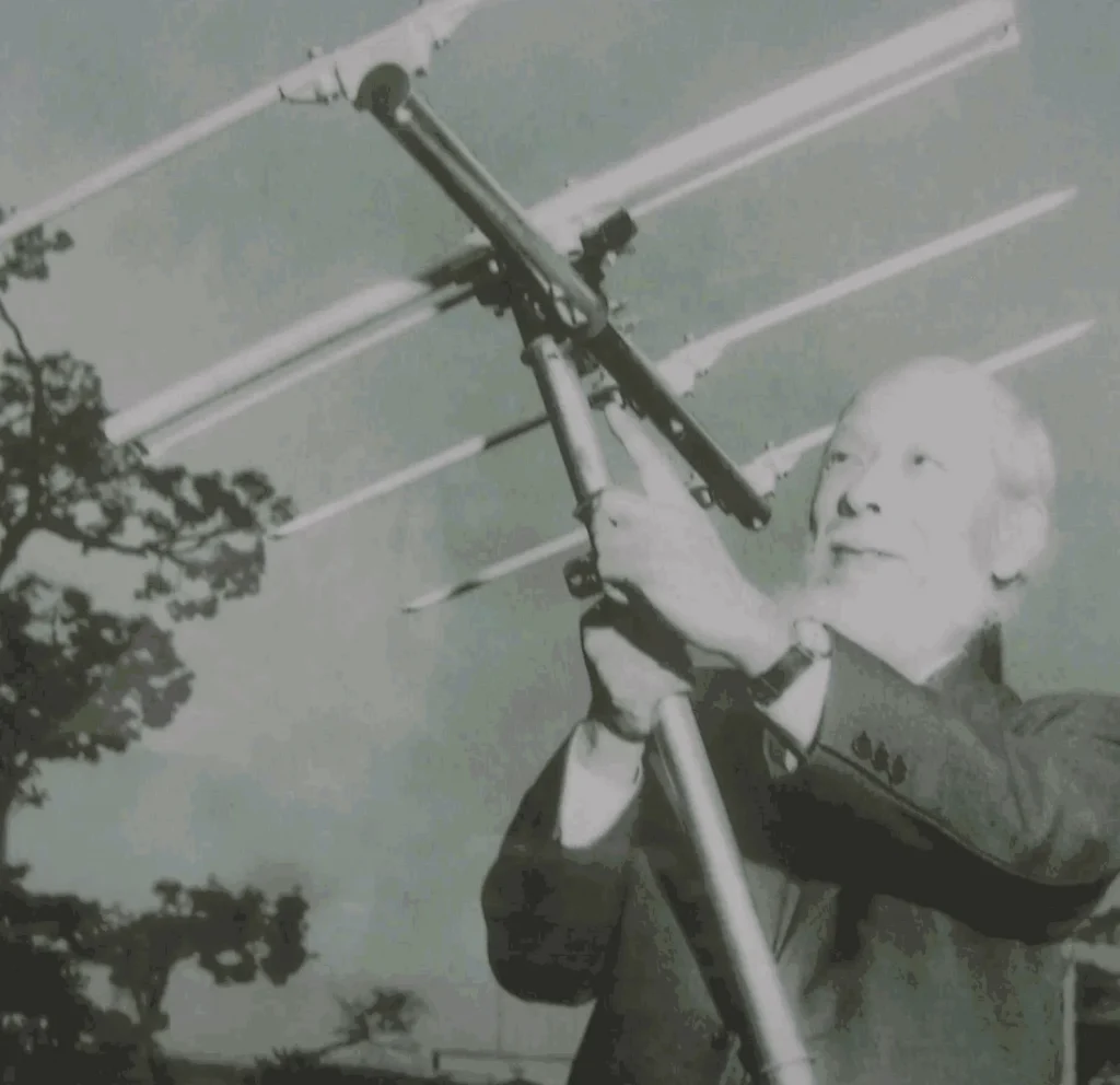
History of the Yagi Antenna
The Yagi antenna was first introduced as an experimental concept in the 1920s at Tohoku Imperial University, Japan. Yagi and Uda discovered that adding passive elements (reflectors and directors) to a driven dipole element increased its directional gain. Initially, the antenna was not widely adopted in Japan but gained international recognition when it was translated into English and used extensively during World War II for radar and military communication applications.

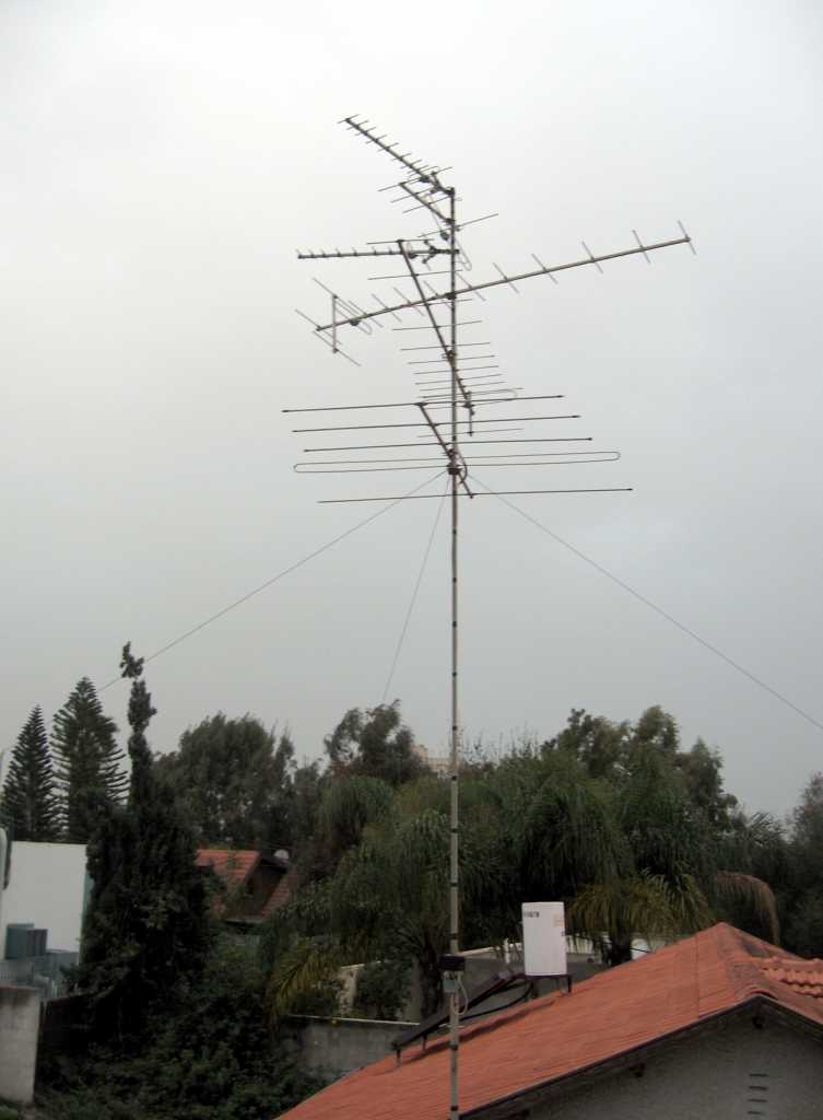
Due to its effectiveness in radio communications, the Yagi antenna became a staple in various applications, including amateur radio, television broadcasting, and scientific research.
Yagi Antenna Structure
A Yagi antenna consists of multiple elements:
- Driven Element (Dipole): The active component that is directly connected to the transmission line.
- Reflector: Positioned behind the dipole, this element reflects signals forward, improving the antenna’s gain.
- Directors: Placed in front of the dipole, these elements focus the signal to enhance directivity.
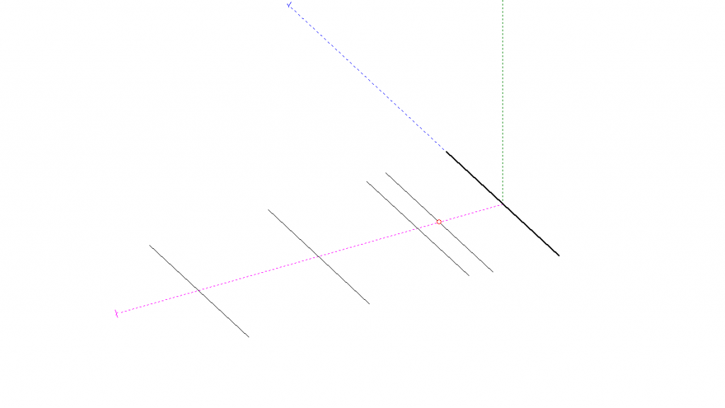
The spacing and lengths of these elements determine the antenna’s impedance, gain, and beamwidth.
Yagi Antenna Design Calculation
The essential parameters for designing a Yagi antenna include:
- Frequency (MHz): Determines the wavelength of operation.
- Number of Elements: More elements result in higher gain and a narrower beam.
- Boom Diameter (BD): The thickness of the supporting structure.
- Element Diameter (ED): The thickness of the conducting elements.
- Material of the Boom: Conductive (metal) or non-conductive (PVC or wood) affects calculations.
The general formula for wavelength (λ) is:
Where:
- λ = Wavelength in meters
- c = Speed of light (299,792,458 m/s)
- f = Frequency in Hz
Each element’s length and spacing are derived from empirical formulas and practical design considerations. The driven element length is typically about 0.47λ, the reflector is 5% longer, and directors are 5% shorter.
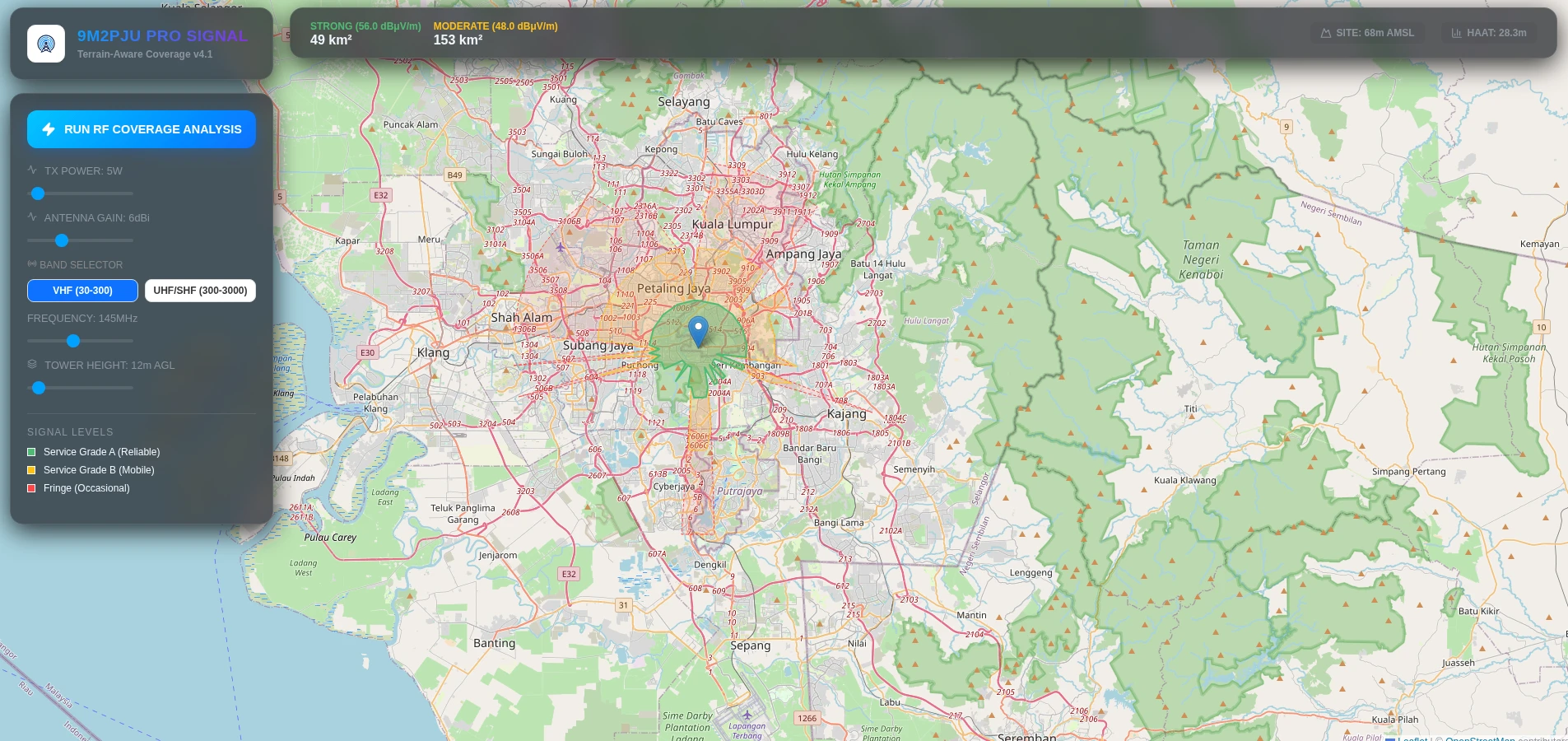
Example Calculation (145.500 MHz, 3 Elements, 20mm Boom, 10mm Elements)
For a 145.500 MHz Yagi antenna with three elements:
- Wavelength: 2060.43 mm
- Boom Length: 649.04 mm
- Reflector: Position 0 mm, Length 999.86 mm
- Dipole: Position 494.50 mm, Length 993.13 mm
- Director 1: Position 649.04 mm, Length 943.52 mm
- Estimated Gain: 6.4 dB
For an online Yagi antenna calculator, visit: Yagi Antenna Calculator.
The Yagi-Uda antenna is an effective directional antenna used in various communication applications. Understanding its design parameters helps in optimizing performance for specific frequency bands. With the help of online calculators, designing a custom Yagi antenna becomes easier, allowing enthusiasts and professionals to build efficient antennas for their needs.


Post Comment