amateur radio
antenna
antenna calculation
ham radio
standing wave ratio
AmateurRadio, antenna101, antennaanalysis, antennaefficiency, antennafundamentals, antennaimpedance, Antennas, antennatheory, DipoleAntenna, electromagneticwaves, hamradio, HF, nanovna, radioantenna, radiocommunication, rfengineering, swr, UHF, VHF, yagianteanna
9M2PJU
0 Comments
Antenna Theory for Radio Communications

If you’ve mastered the basics—like wavelength, antenna length, and SWR—it’s time to take a deeper dive into antenna theory. In this article, we’ll move beyond simple definitions and explore the concepts that really impact your signal: impedance, radiation efficiency, gain, polar plots, and practical matching techniques.
📡 Antenna Impedance and Reactance
Every antenna has a feedpoint impedance, which is a combination of:
- Resistance (R) – includes radiation resistance (good) and loss resistance (bad)
- Reactance (X) – caused by stored electric or magnetic energy (capacitive or inductive)
The total impedance is:
Z = R + jX
Example:
A typical half-wave dipole has an impedance of around 72Ω resistive at its resonant frequency. But off-resonance, you might see a high or low reactance, making matching more difficult.
📉 SWR vs. Impedance Matching
Standing Wave Ratio (SWR) is a measure of how well your antenna system is matched to the characteristic impedance of your transmission line, usually 50Ω.
- 1:1 SWR = perfect match
- >2:1 SWR = reflections start causing noticeable power loss and heating in the feedline
However, SWR alone doesn’t tell the whole story. A 1:1 match through a lossy tuner into a poorly performing antenna isn’t better than a 1.8:1 match into a well-built resonant antenna.
✅ Aim for a good match with minimal losses, not just a low SWR.
📈 Radiation Resistance and Efficiency
Radiation resistance is the part of the feedpoint resistance that contributes to actual radiation of RF energy, not heat.
Efficiency = Rradiation / (Rradiation + Rloss)
- A full-size dipole at resonance might have a radiation resistance of ~72Ω and almost no loss resistance—very efficient.
- A shortened mobile whip on 40m might have a radiation resistance of only 5Ω and 20Ω of loss resistance—very inefficient (only 20% of power radiated!).
📈 Antenna Gain and Polar Plots
Gain measures how much an antenna concentrates energy in a particular direction compared to a reference.
- dBi = gain relative to an isotropic source (theoretical point radiator)
- dBd = gain relative to a dipole (2.15 dB less than dBi)
Example:
A Yagi antenna might have 9 dBi gain – it focuses energy forward and minimizes it elsewhere.
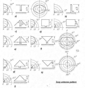
Polar plots show this directional behavior:
- Omnidirectional antennas (e.g., verticals) have a doughnut-shaped pattern
- Directional antennas (e.g., beams, Yagis) focus energy into a lobe or multiple lobes
⚙️ Practical Matching Techniques
Sometimes you need to transform impedance to match your transceiver and minimize reflected power.
Common methods:
- Balun (Balanced-to-Unbalanced Transformer): Converts balanced antennas like dipoles to work with unbalanced coax.
- Unun (Unbalanced-to-Unbalanced): Used for end-fed antennas or long wires.
- LC Networks: Custom inductors and capacitors can create matching circuits.
- Coaxial Stubs or Line Sections: Transmission line lengths can act as impedance transformers.
- ATUs (Antenna Tuning Units): Match almost anything, but can introduce loss, especially in lossy feedlines like RG-58.
🧠 Real-World Considerations
🔹 Ground Effects
Antennas near the ground interact with the earth’s conductivity and permittivity. For HF verticals, a good radial system dramatically improves performance.
🔹 Height and Environment
- VHF/UHF: Line-of-sight is king. Height = range.
- HF: Height affects takeoff angle. Lower antennas favor NVIS (local), higher antennas favor DX (low angle).
🔹 Feedline Loss
Use low-loss cable (e.g., LMR-400 or RG-213) for VHF/UHF runs or long HF runs. Loss becomes significant at higher frequencies.
🛠 Tools for Analysis
- NanoVNA: Affordable vector network analyzer. Measures complex impedance, SWR, S11.
- SWR meters / Antenna Analyzers: Great for tuning.
- 4NEC2 / MMANA-GAL: Antenna modeling software. Simulate radiation patterns, impedance, and more.
- SWR apps: Many handheld devices now offer digital SWR meters and spectrum tools.
🔚 Conclusion
Antenna theory bridges the gap between just “cutting a wire and making contacts” and truly engineering your signal. Understanding impedance, gain, efficiency, and matching methods empowers you to design antennas that perform better, go farther, and waste less power.


Post Comment