Oscilloscope Usages for Amateur Radio
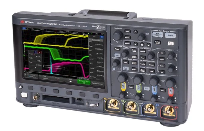
An oscilloscope is one of the most useful test instruments an amateur radio operator can own. It lets you see electrical signals instead of only measuring them as numbers.
A multimeter tells you, “There is 13.8 volts here.”
An oscilloscope shows you, “This voltage is clean,” “this audio is distorted,” “this power supply has ripple,” or “this signal is pulsing.”
For amateur radio, an oscilloscope is useful for checking audio, power supplies, keying circuits, digital signals, modulation, and some RF work. You do not need to be an engineer to use one. Start with simple measurements, learn what normal signals look like, and build confidence from there.
What an Oscilloscope Does
An oscilloscope displays voltage over time.
The screen has two main directions:
Vertical = voltage
Horizontal = time
If the line goes up, voltage is higher.
If the line goes down, voltage is lower.
If the pattern repeats, you are looking at a waveform.
Common waveforms include:
- sine wave
- square wave
- audio waveform
- RF carrier
- pulse
- noise
- ripple
In radio work, this helps you understand what is really happening inside your station or circuit.
Why Amateur Radio Operators Use Oscilloscopes
The most common uses are:
- checking power supply ripple
- viewing microphone audio
- checking audio distortion
- testing CW keying waveform
- checking PTT or switching signals
- troubleshooting digital mode interfaces
- viewing modulation envelope
- checking oscillator output
- comparing input and output of filters
- troubleshooting kits and homebrew circuits
For most hams, the oscilloscope is not mainly for measuring transmitter power. A wattmeter is better for that. The oscilloscope is for seeing signal shape, timing, noise, and distortion.
Basic Controls You Need to Know
Volts Per Division
This controls the vertical scale.
Example:
1 V/divmeans each vertical box on the screen equals 1 volt.
If the signal is too tall and goes off the screen, increase the volts/div setting.
If the signal is too small, decrease it.
Beginner hint:
Start with a higher volts/div setting first, then zoom in.Time Per Division
This controls the horizontal scale.
Example:
1 ms/divmeans each horizontal box equals 1 millisecond.
Use a slower time setting for audio and slow signals.
Use a faster time setting for RF, pulses, and digital signals.
Beginner hint:
If the waveform looks like a blur, adjust time/div.Trigger
The trigger makes the waveform hold still on the screen.
Without triggering, the waveform may slide around.
Set trigger to:
Edge trigger
Rising edge
Auto mode
for most beginner measurements.
Beginner hint:
If the trace will not stay still, adjust trigger level.Probe Setting: 1x and 10x
Most oscilloscope probes have a switch:
1x
10x
Use 10x most of the time.
A 10x probe loads the circuit less and is safer for many measurements. It also allows higher voltage measurement.
Important:
If the probe is set to 10x, the oscilloscope channel must also be set to 10x.Otherwise, the voltage reading will be wrong.
Safety First
This part matters.
Most bench oscilloscopes have the probe ground clip connected to earth ground through the power cord. If you clip it to the wrong point in a live circuit, you can create a short circuit.
Safe beginner rule:
Connect the ground clip only to circuit ground.For amateur radio gear, that usually means chassis ground, DC negative, or the shield side of a connector.
Be extra careful with:
- mains-powered power supplies
- tube radios
- high-voltage amplifiers
- switching power supplies
- unknown equipment
Beginner warning:
Do not clip oscilloscope ground to live AC mains.If you are not sure where ground is, stop and check the circuit diagram first.
Use 10x Probe and Start High
Before connecting the probe:
- Set probe to
10x. - Set oscilloscope channel to
10x. - Set coupling to
DC. - Set volts/div high enough.
- Connect ground clip to circuit ground.
- Touch probe tip to the test point.
- Adjust volts/div and time/div.
This avoids many beginner mistakes.
AC Coupling vs DC Coupling
Oscilloscopes usually have DC coupling and AC coupling.
DC Coupling
DC coupling shows everything:
DC voltage + AC signalUse DC coupling when checking:
- power supply voltage
- logic levels
- PTT lines
- bias voltage
- battery voltage
- DC offset
AC Coupling
AC coupling blocks DC and shows only the changing part of the signal.
Use AC coupling when checking:
- audio waveform riding on DC
- small ripple on a DC supply
- hum
- noise
- modulation audio
Example:
A 13.8 V power supply may have small ripple. With DC coupling, the ripple may be hard to see because the DC voltage is much larger. With AC coupling, the oscilloscope removes the DC part so you can see the ripple clearly.
Beginner hint:
Use DC coupling first. Use AC coupling when you want to zoom in on small AC variations.Common Amateur Radio Uses
1. Checking Power Supply Ripple
A clean power supply should provide steady DC. Ripple is unwanted AC riding on the DC.
How to check:
- Connect probe ground to power supply negative.
- Touch probe tip to positive output.
- Start with DC coupling to confirm voltage.
- Switch to AC coupling.
- Set a sensitive volts/div scale.
- Look for ripple or noise.
What you may see:
- flat line = clean supply
- repeating wave = ripple
- spikes = switching noise or interference
Why it matters:
Power supply ripple can cause hum, noise, unstable transmit audio, or strange radio behavior.
Beginner hint:
Check the supply while the radio is transmitting, not only while receiving.The supply may look clean with no load but noisy under load.
2. Viewing Microphone Audio
An oscilloscope can show whether your microphone audio is clean or distorted.
Where to check:
- microphone output
- audio interface output
- radio accessory connector
- digital mode interface
What clean audio looks like:
- smooth waveform
- no flat tops
- no sharp clipping
What bad audio looks like:
- flattened peaks
- excessive level
- buzzing or hum
- noise when you are not speaking
Beginner hint:
If the waveform has flat tops, the audio is clipping.Clipped audio sounds harsh and can create splatter or poor digital decoding.
3. Checking Digital Mode Audio
Digital modes such as FT8, JS8Call, RTTY, packet, and Winlink depend on clean audio levels.
Use the oscilloscope to check:
- computer audio output
- USB sound card output
- interface output
- radio audio input
Look for:
- clean waveform
- no clipping
- no excessive hum
- stable level
Beginner hint:
For digital modes, clean audio is better than loud audio.Overdriving the radio can make your signal wide and dirty.
4. Checking CW Keying
For CW, an oscilloscope can show the shape of the keyed signal or keying control line.
A good CW waveform should not switch too abruptly at the RF envelope. Very sharp keying can cause key clicks.
You can check:
- key line voltage
- keyer output
- transmitter RF envelope with proper sampler
- QSK timing
Beginner hint:
Do not connect the oscilloscope directly to transmitter RF output unless you know the voltage and use proper attenuation.Use a dummy load and RF sampler or attenuator.
5. Viewing RF Modulation Envelope
For AM or SSB testing, an oscilloscope can show the RF envelope when connected safely through a sampler or attenuator.
For AM:
- smooth envelope = good modulation
- pinched or flattened envelope = overmodulation
- uneven shape = distortion or drive problem
For SSB:
- waveform changes with speech
- no steady carrier in normal SSB voice
- excessive flat topping suggests overdrive
Beginner hint:
A normal oscilloscope input is not meant to take full transmitter power.Never connect a transmitter output directly to the scope input. Use a dummy load plus suitable attenuator or RF sampler.
6. Checking PTT and Switching Lines
PTT lines are simple but important. An oscilloscope can show whether the signal changes cleanly and at the right time.
Use it to check:
- PTT from computer interface
- foot switch
- relay timing
- sequencer timing
- amplifier keying line
- transverter switching
Look for:
- correct voltage level
- clean transition
- no bouncing
- correct timing delay
Beginner hint:
For relays and switching, the timing may matter more than the voltage.This is especially important with amplifiers, preamps, and transverters.
7. Testing Oscillators and Homebrew Circuits
If you build kits or homebrew radios, an oscilloscope helps you see whether circuits are alive.
You can check:
- audio oscillator output
- crystal oscillator output
- VFO output
- clock signals
- mixer signals
- filter input and output
- amplifier stages
Look for:
- signal present or absent
- correct frequency range
- rough signal shape
- unexpected distortion
- too much or too little level
Beginner hint:
First ask: is the signal there? Then ask: is it the right shape and level?8. Comparing Filter Input and Output
Filters are common in radio: audio filters, IF filters, low-pass filters, band-pass filters, and notch filters.
With a signal generator and oscilloscope, you can compare:
- signal before the filter
- signal after the filter
If the output is much smaller at a certain frequency, the filter is attenuating that frequency.
Beginner hint:
A two-channel oscilloscope is useful because you can view input and output at the same time.Measuring Frequency and Period
Many oscilloscopes can measure frequency automatically.
You can also estimate it manually.
Formula:
Frequency = 1 / PeriodIf one cycle takes:
1 msthen:
Frequency = 1 / 0.001 = 1000 HzFor audio tones, this is very useful.
For RF, make sure your oscilloscope bandwidth is high enough.
Oscilloscope Bandwidth
Oscilloscopes have bandwidth ratings, such as:
50 MHz
100 MHz
200 MHz
This tells you the highest frequency the scope can display reasonably well.
Beginner rule:
Use a scope with bandwidth at least 5 times higher than the signal frequency if you care about waveform shape.Example:
For a 10 MHz signal, a 50 MHz scope is a practical minimum for seeing the shape.
For 145 MHz VHF RF, many beginner scopes are not suitable for direct waveform viewing.
But even a basic scope is still very useful for:
- DC
- audio
- power supplies
- switching
- keying
- control lines
- digital interfaces
Important: Do Not Overload the Scope
Most oscilloscope inputs are limited, often around:
300 V maximumor less, depending on the model and probe.
RF transmitter outputs can produce high voltage.
Example:
100 W into 50 ohms = about 70.7 V RMSPeak voltage is higher than RMS. With modulation or mismatch, it can be even higher.
Beginner rule:
Do not connect transmitter RF output directly to an oscilloscope.Use:
- dummy load
- attenuator
- RF sampler
- proper rated probe
- correct scope input setting
Best Beginner Setup for Ham Radio
A practical beginner setup:
- digital oscilloscope,
50 MHzto100 MHz - two channels
10xprobes- dummy load
- RF sampler or attenuator
- BNC adapters
- short coax leads
- audio test cable
- signal generator if available
You do not need the most expensive oscilloscope. For many amateur radio tasks, a basic digital scope is already very useful.
Quick Beginner Checklist
Before measuring:
What signal am I measuring?
What voltage might be present?
Where is circuit ground?
Is the probe set to 10x?
Is the scope channel set to 10x?
Should I use AC or DC coupling?
Is the frequency within the scope bandwidth?
Could this damage the scope?
If unsure, start with the safest settings:
10x probe
High volts/div
DC coupling
Ground clip to circuit ground
Dummy load for transmit tests
No direct RF transmitter output
Common Beginner Mistakes
Avoid these:
- connecting scope ground to the wrong point
- measuring mains circuits casually
- using 1x probe when 10x is better
- forgetting to set the channel to match the probe
- connecting transmitter RF directly to the scope
- trusting waveform shape beyond scope bandwidth
- using long ground leads at RF
- ignoring probe compensation
- measuring without a dummy load during transmit tests
Probe Compensation
Most probes need compensation adjustment.
To check it:
- Connect probe to the oscilloscope calibration output.
- Display the square wave.
- Adjust the small screw on the probe.
- Make the square wave corners look clean and square.
If compensation is wrong, square waves may look rounded or overshot.
Beginner hint:
Compensate your probe before serious measurements.Final Advice
An oscilloscope is not just for experts. For amateur radio, it is one of the best tools for learning what signals really look like.
Start with safe, simple measurements:
- power supply ripple
- microphone audio
- digital mode audio
- PTT lines
- CW keying
- kit oscillator output
Do not rush into high-power RF measurements. Use a dummy load, attenuator, or RF sampler when transmitting.
The most important lesson is simple:
A multimeter gives you a number.
An oscilloscope shows you the behavior.
Once you can see the behavior, troubleshooting becomes much easier.

Post Comment