amateur radio
ham radio
radio amatur
amateur radio guide, amateur radio units, antenna gain, dB in amateur radio, dBi vs dBd, dBm explained, ham radio basics, ham radio units, radio frequency units, receiver sensitivity, RF measurements, SINAD explained, SNR explained, SWR explained, watts volts ohms
9M2PJU
0 Comments
Amateur Radio Units Explained: dB, dBm, Watts, SWR, SNR, SINAD, dBi and More
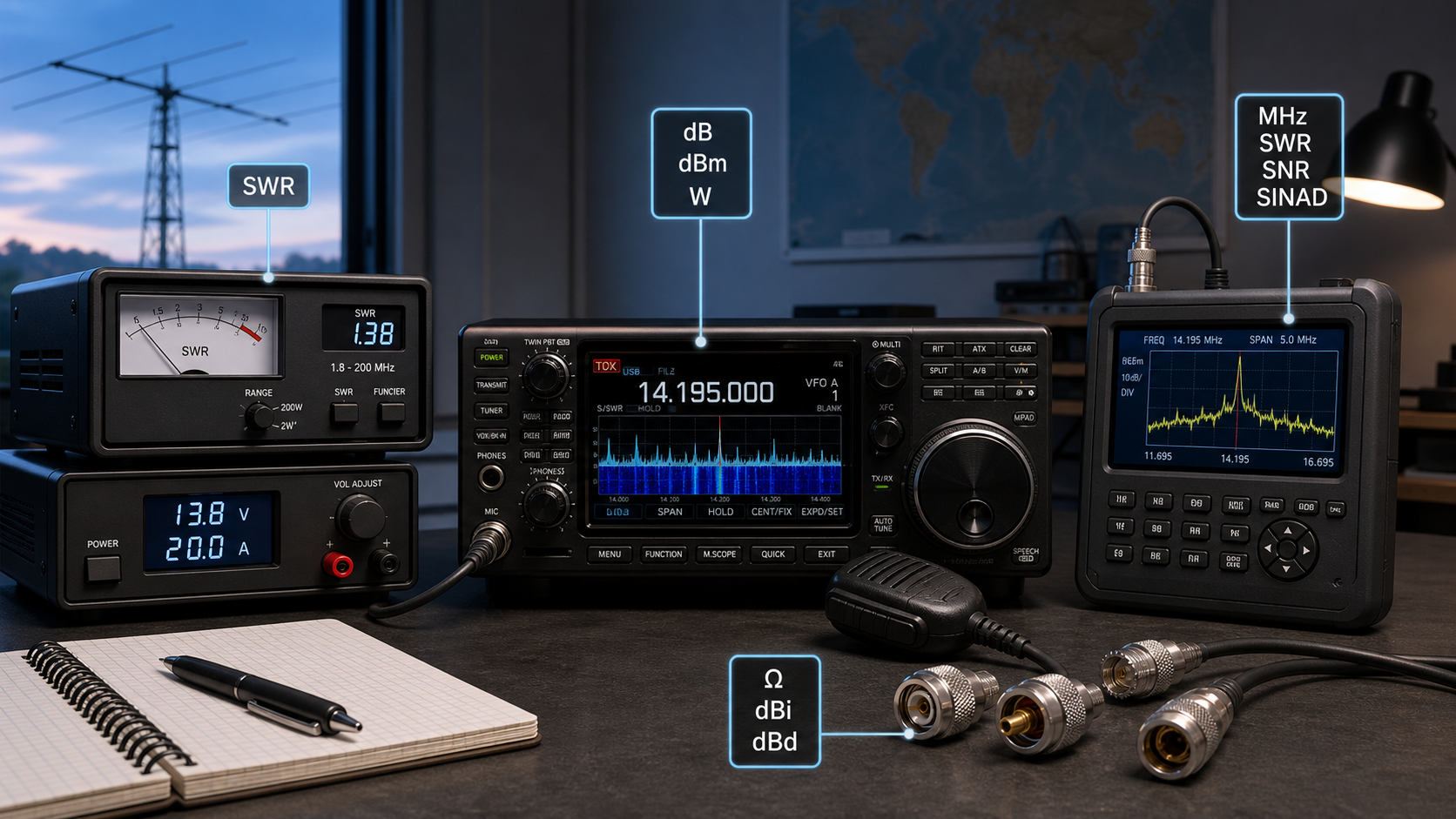
Amateur radio is full of numbers: watts, volts, ohms, decibels, megahertz, microvolts, SWR, SNR, SINAD, dBi, dBd, and many more. At first they look like a pile of technical jargon, but they are really just the language of radio. Once you understand the units, you can read radio specifications, choose antennas, estimate station performance, troubleshoot problems, and communicate more precisely.
This article covers the most important units and measurements every amateur radio operator should know.
1. Frequency: Hz, kHz, MHz, GHz
Frequency is one of the most basic concepts in radio. It describes how many cycles per second a signal makes.
The SI unit is the hertz, written as Hz.
Common radio units:
| Unit | Meaning | Example |
|---|---|---|
Hz | hertz | audio tone, very low frequency |
kHz | kilohertz, 1,000 Hz | 7,100 kHz |
MHz | megahertz, 1,000,000 Hz | 145.500 MHz |
GHz | gigahertz, 1,000,000,000 Hz | 2.4 GHz |
Amateur bands are usually described by either frequency or wavelength.
Examples:
| Band | Approximate Frequency |
|---|---|
160 m | 1.8 MHz |
80 m | 3.5 MHz |
40 m | 7 MHz |
20 m | 14 MHz |
2 m | 144 MHz |
70 cm | 430 MHz |
Frequency tells you where you are transmitting or receiving. It also affects propagation, antenna size, bandwidth, and licensing rules.
2. Wavelength: m, cm, mm
Wavelength is the physical length of one complete radio wave cycle. The SI unit is the meter, written as m.
Radio operators often use wavelength names for bands:
| Band Name | Wavelength |
|---|---|
40 m | about 40 meters |
20 m | about 20 meters |
2 m | about 2 meters |
70 cm | about 0.7 meters |
23 cm | about 0.23 meters |
The relationship between frequency and wavelength is:
wavelength in meters = 300 / frequency in MHzExamples:
145 MHz: 300 / 145 = about 2.07 m
433 MHz: 300 / 433 = about 0.69 m
This matters because antenna size is usually related to wavelength. A half-wave dipole for 40 m is physically much larger than a half-wave antenna for 2 m.
3. Power: W, mW, kW
Power tells you how much energy your transmitter sends out. The SI unit is the watt, written as W.
Common units:
| Unit | Meaning |
|---|---|
mW | milliwatt, 0.001 W |
W | watt |
kW | kilowatt, 1,000 W |
Examples:
| Equipment | Typical Power |
|---|---|
| Handheld radio | 1 W to 5 W |
| Mobile VHF/UHF radio | 25 W to 50 W |
| HF transceiver | 100 W |
| QRP station | usually 5 W or less |
| Linear amplifier | hundreds of watts or more |
More power can help, but it is not magic. Antenna efficiency, feedline loss, receiver noise, propagation, and operating skill often matter more than raw watts.
A useful rule:
Doubling power = +3 dB
Ten times power = +10 dB
So going from 5 W to 50 W is a 10 dB increase. Going from 50 W to 100 W is only 3 dB.
4. Voltage: V, mV, µV
Voltage is electrical pressure. The SI unit is the volt, written as V.
Common units:
| Unit | Meaning |
|---|---|
µV | microvolt, one millionth of a volt |
mV | millivolt, one thousandth of a volt |
V | volt |
kV | kilovolt |
In amateur radio, voltage appears in several places:
| Use | Example |
|---|---|
| DC power supply | 13.8 V |
| Battery voltage | 12 V, LiFePO4 13.2 V |
| Receiver sensitivity | 0.16 µV |
| RF voltage | depends on power and impedance |
Many mobile and base radios are designed for about 13.8 V DC, because that is typical of a vehicle electrical system while charging.
Receiver sensitivity is often stated in microvolts. For example:
0.18 µV @ 12 dB SINADThat means the receiver can detect a very weak signal and still produce usable audio.
5. Current: A, mA
Current is the flow of electric charge. The SI unit is the ampere, written as A.
Common units:
| Unit | Meaning |
|---|---|
mA | milliampere |
A | ampere |
Examples:
| Device | Typical Current |
|---|---|
| Handheld receive mode | tens to hundreds of mA |
| Handheld transmit mode | around 1 A to 2 A |
| 50 W mobile radio transmit | around 10 A to 15 A |
| 100 W HF radio transmit | around 20 A to 25 A |
Power, voltage, and current are related:
Power = Voltage × Current
W = V × A
Example:
13.8 V × 20 A = 276 W input powerThe RF output may be 100 W, because the radio is not 100% efficient. Some energy becomes heat.
6. Resistance and Impedance: Ω
Resistance and impedance are measured in ohms, written as Ω.
Resistance applies mainly to DC circuits. Impedance applies to AC and RF circuits, where capacitance and inductance also matter.
Common amateur radio impedance values:
| System | Typical Impedance |
|---|---|
| Most amateur coax systems | 50 Ω |
| TV coax | 75 Ω |
| Balanced feedline | 300 Ω, 450 Ω, 600 Ω |
| Speaker audio | 4 Ω, 8 Ω |
Most modern amateur radios expect a 50 Ω antenna system. If the antenna system is not close to 50 Ω, the radio may reduce power or require an antenna tuner.
7. SWR: Standing Wave Ratio
SWR means Standing Wave Ratio. It describes how well the antenna system matches the transmitter and feedline.
SWR is written as a ratio:
1.0:1
1.5:1
2.0:1
3.0:1
General guide:
| SWR | Meaning |
|---|---|
1.0:1 | perfect match |
1.5:1 | very good |
2.0:1 | usually acceptable |
3.0:1 | high; check antenna/feedline |
above 3.0:1 | may be unsafe for some radios |
SWR does not directly tell you whether an antenna is “good.” It tells you about impedance match. A dummy load can have excellent SWR but radiates almost nothing. A real antenna can have a decent SWR but still be inefficient if badly placed, lossy, or poorly built.
8. Decibel: dB
The decibel, written as dB, is one of the most important units in radio.
Strictly speaking, dB is not an SI unit. It is a logarithmic ratio. It compares one value to another.
In radio, dB is used for:
- antenna gain
- feedline loss
- amplifier gain
- filter attenuation
- signal strength
- path loss
- receiver performance
Useful dB rules:
| Change | Meaning |
|---|---|
+3 dB | about double the power |
-3 dB | about half the power |
+6 dB | about 4 times the power |
+10 dB | 10 times the power |
-10 dB | one tenth the power |
+20 dB | 100 times the power |
-20 dB | one hundredth the power |
Example:
If your coax has 3 dB loss, about half your power is lost in the feedline.
50 W transmitter power
3 dB feedline loss
about 25 W reaches the antenna
The decibel is powerful because gains and losses can be added.
Example:
Transmitter power: 50 W
Feedline loss: -2 dB
Antenna gain: +6 dBi
Net antenna-side gain effect: +4 dB
9. dBm and dBW
dBm and dBW are decibel units with fixed references.
| Unit | Reference |
|---|---|
dBm | relative to 1 milliwatt |
dBW | relative to 1 watt |
Common values:
| Power | dBm | dBW |
|---|---|---|
1 mW | 0 dBm | -30 dBW |
10 mW | 10 dBm | -20 dBW |
100 mW | 20 dBm | -10 dBW |
1 W | 30 dBm | 0 dBW |
10 W | 40 dBm | 10 dBW |
100 W | 50 dBm | 20 dBW |
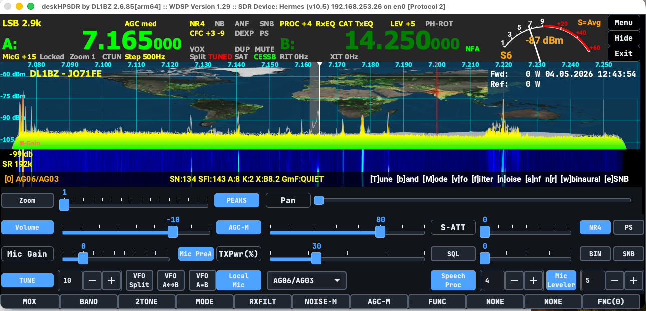
dBm is very common in receiver specs, spectrum analyzers, SDR software, link budgets, and weak-signal work.
Example:
-120 dBm = very weak signal
-90 dBm = stronger signal
-60 dBm = strong local signal
Less negative is stronger.
10. Antenna Gain: dBi and dBd
Antenna gain describes how an antenna concentrates radio energy in a particular direction compared with a reference antenna.
Two common units are dBi and dBd.
| Unit | Reference |
|---|---|
dBi | gain compared with an isotropic radiator |
dBd | gain compared with a half-wave dipole |
An isotropic radiator is a theoretical antenna that radiates equally in all directions. It is useful for math, but it does not physically exist.
A half-wave dipole is a real, common antenna.
Relationship:
dBi = dBd + 2.15
dBd = dBi - 2.15
Example:
Antenna gain = 5 dBd
Same gain = 7.15 dBi
Be careful when comparing antennas. A manufacturer using dBi may make the number look larger than one using dBd.
11. EIRP and ERP
EIRP means Effective Isotropic Radiated Power.
It is the apparent radiated power compared with an isotropic antenna.
ERP means Effective Radiated Power.
It is the apparent radiated power compared with a half-wave dipole.
These are important for regulations, repeater planning, satellite work, and link budgets.
Basic idea:
EIRP = transmitter power - feedline loss + antenna gain in dBi
ERP  = transmitter power - feedline loss + antenna gain in dBd
Example:
Transmitter: 50 W
Feedline loss: 3 dB
Antenna gain: 6 dBi
Power after feedline loss:
50 W - 3 dB = about 25 WAntenna gain:
25 W + 6 dB = about 100 W EIRP12. Bandwidth: Hz, kHz, MHz
Bandwidth is the amount of frequency space a signal occupies.
Common examples:
| Mode | Typical Bandwidth |
|---|---|
| CW | very narrow, often a few hundred Hz |
| SSB voice | about 2.4 kHz to 3 kHz |
| AM voice | about 6 kHz or more |
| FM narrowband | around 12.5 kHz channel spacing |
| FM wideband | around 25 kHz channel spacing |
| Digital modes | varies widely |
Bandwidth matters because radio spectrum is shared. A narrow signal uses less spectrum and may work better under weak conditions. A wide signal may carry better audio or more data but takes more space.
13. Signal Reports: RST and S-Units
Amateur radio commonly uses signal reports.
For CW and voice, the classic report is RST:
| Letter | Meaning |
|---|---|
R | readability |
S | strength |
T | tone, mainly for CW |
Example:
59
599
57
For voice, 59 means perfectly readable and strong. In contests, 59 is often exchanged quickly and may not be a precise measurement.
Many receivers also show S-units on an S-meter.
A common convention:
1 S-unit ≈ 6 dB
S9 on HF ≈ -73 dBm
S9 on VHF/UHF ≈ -93 dBm
This is a guideline. Many radio S-meters are not perfectly calibrated.
Above S9, reports are often given in dB:
S9 + 10 dB
S9 + 20 dB
S9 + 40 dB
14. SNR: Signal-to-Noise Ratio
SNR means Signal-to-Noise Ratio.
It compares the wanted signal with the noise level.
SNR = signal level compared with noise levelIt is usually measured in dB.
Examples:
| SNR | Meaning |
|---|---|
0 dB | signal and noise are about equal |
10 dB | signal is clearly above noise |
20 dB | good copy |
30 dB | very clean signal |
SNR is especially important for:
- HF weak-signal work
- digital modes such as FT8, JS8Call, packet, APRS, Winlink
- satellite communication
- EME
- SDR receiver displays
- link budget calculations
Digital modes often work at lower SNR than voice because computers can decode weak structured signals.
15. SINAD
SINAD means:
Signal + Noise + Distortion
divided by
Noise + Distortion
It is used mainly in receiver sensitivity testing, especially for FM voice receivers.
A common specification:
0.18 µV for 12 dB SINADThis means that with a signal of 0.18 microvolts, the receiver produces audio with 12 dB SINAD, which is considered a usable audio benchmark.
When comparing receivers:
0.16 µV @ 12 dB SINADis generally more sensitive than:
0.25 µV @ 12 dB SINADbecause less signal is needed to reach the same audio quality.
16. Noise Figure: NF
Noise figure, written as NF, describes how much noise a receiver, preamp, or amplifier adds to a signal.
It is measured in dB.
Lower is better.
Examples:
| Noise Figure | Meaning |
|---|---|
0.5 dB | excellent |
1 dB | very good |
3 dB | moderate |
6 dB | noisy |
Noise figure is especially important at VHF, UHF, microwave, satellite, and weak-signal operation. On lower HF bands, atmospheric noise may dominate, so receiver noise figure is often less critical.
17. Noise Floor: dBm
The noise floor is the background noise level in a receiver or measurement system.
It is often shown in dBm.
Example:
Noise floor: -120 dBm
Signal: -100 dBm
SNR: 20 dB
A lower noise floor allows weaker signals to be detected. However, real-world noise from power supplies, electronics, thunderstorms, solar activity, and urban environments can raise the effective noise floor.
18. Return Loss
Return loss is another way to describe antenna mismatch. It is measured in dB.
Higher return loss is better.
Approximate comparison:
| SWR | Return Loss |
|---|---|
1.0:1 | infinite, perfect |
1.5:1 | about 14 dB |
2.0:1 | about 9.5 dB |
3.0:1 | about 6 dB |
Many antenna analyzers and VNAs show return loss as well as SWR.
19. Capacitance: F, µF, nF, pF
Capacitance is measured in farads, written as F.
In radio, practical values are usually much smaller:
| Unit | Meaning |
|---|---|
µF | microfarad |
nF | nanofarad |
pF | picofarad |
Capacitors are used in:
- filters
- antenna tuners
- matching networks
- oscillators
- power supply filtering
- coupling and bypass circuits
Examples:
100 pF tuning capacitor
0.1 µF bypass capacitor
10 µF electrolytic capacitor
20. Inductance: H, mH, µH
Inductance is measured in henrys, written as H.
Common radio values:
| Unit | Meaning |
|---|---|
mH | millihenry |
µH | microhenry |
nH | nanohenry |
Inductors are used in:
- antenna loading coils
- filters
- traps
- matching networks
- RF chokes
- oscillators
Examples:
2.2 µH coil
100 µH RF choke
Capacitors and inductors together form resonant circuits, which are central to radio tuning and filtering.
21. Battery Capacity: Ah and Wh
Battery capacity is commonly given in amp-hours, written as Ah.
Example:
12 V 20 Ah batteryThis means the battery can theoretically supply:
20 A for 1 hour
or
1 A for 20 hours
In practice, usable capacity depends on battery chemistry, discharge rate, temperature, and cutoff voltage.
A better energy unit is watt-hour, written as Wh.
Wh = V × AhExample:
12.8 V × 20 Ah = 256 WhFor emergency communication and portable radio, Wh is often more useful than Ah, because it includes voltage.
22. Temperature: °C and K
Temperature is commonly measured in degrees Celsius, written as °C.
Examples:
Radio operating temperature: -10 °C to +60 °C
Battery temperature limit: 0 °C to 45 °C while charging
The SI base unit is kelvin, written as K.
Kelvin is used in technical radio calculations involving thermal noise.
Important idea:
Higher temperature = more thermal noiseMost amateur operators use Celsius day to day, but kelvin appears in receiver noise and microwave engineering.
23. Time: s, ms, µs, UTC
Time is measured in seconds, written as s.
Common units:
| Unit | Meaning |
|---|---|
s | second |
ms | millisecond |
µs | microsecond |
Time matters for:
- digital modes
- packet timing
- propagation delay
- satellite passes
- logging
- contests
- emergency nets
Amateur radio commonly uses UTC, Coordinated Universal Time, for logging and international contacts.
Example log entry:
2026-06-29 1415 UTC
14.074 MHz
FT8
9M2PJU
-12 dB
Using UTC avoids confusion between time zones.
24. Data Rate: bps and Baud
Digital radio uses data rates.
| Unit | Meaning |
|---|---|
bps | bits per second |
baud | symbols per second |
They are related, but not always the same.
If each symbol carries one bit:
baud = bpsIf each symbol carries multiple bits:
bps can be higher than baudExamples:
| Mode/System | Related Unit |
|---|---|
| Packet radio | 1200 bps, 9600 bps |
| RTTY | baud rate, shift |
| Digital voice | bit rate |
| Modems | baud and bps |
25. Field Strength: V/m and dBµV/m
Field strength describes the strength of an electromagnetic field at a location.
Common units:
| Unit | Meaning |
|---|---|
V/m | volts per meter |
mV/m | millivolts per meter |
µV/m | microvolts per meter |
dBµV/m | decibels relative to 1 microvolt per meter |
Field strength is used in:
- coverage prediction
- repeater studies
- EMC/RFI work
- broadcast engineering
- regulatory measurements
Most casual amateur operators do not use field strength daily, but it is important for interference investigations and serious station engineering.
26. Modulation Measurements
Several units and ratios describe modulation quality.
Deviation
FM deviation is measured in Hz or kHz.
Example:
±5 kHz deviation
±2.5 kHz deviation
Too much deviation causes splatter or distortion. Too little deviation makes audio weak.
Modulation Percentage
AM modulation is often expressed as a percentage.
100% modulationOvermodulation causes distortion and unwanted emissions.
THD
THD means Total Harmonic Distortion.
It is usually given as a percentage or in dB.
Lower THD means cleaner audio or cleaner signal reproduction.
27. Digital Quality Units: BER, MER, Eb/N0
Digital communication introduces more quality measurements.
| Unit | Meaning |
|---|---|
BER | Bit Error Rate |
PER | Packet Error Rate |
MER | Modulation Error Ratio |
Eb/N0 | Energy per bit to noise density ratio |
C/N | Carrier-to-noise ratio |
C/N0 | Carrier-to-noise density ratio |
For most amateur operators, BER is the easiest to understand.
Example:
BER = 1 × 10^-5This means about 1 bit error in 100,000 bits.
Lower BER is better.
These measurements are common in digital voice, satellites, microwave links, and data systems.
28. Common Prefixes
SI prefixes are essential in radio.
| Prefix | Symbol | Multiplier |
|---|---|---|
| pico | p | 10^-12 |
| nano | n | 10^-9 |
| micro | µ | 10^-6 |
| milli | m | 10^-3 |
| kilo | k | 10^3 |
| mega | M | 10^6 |
| giga | G | 10^9 |
Examples:
100 pF
2.2 µH
13.8 V
500 mA
7 MHz
2.4 GHz
Be careful with capital letters:
m = milli
M = mega
So:
mW = milliwatt
MW = megawatt
Those are very different.
29. Quick Reference Table
| Measurement | Unit | Used For |
|---|---|---|
| Frequency | Hz, kHz, MHz, GHz | operating frequency |
| Wavelength | m, cm | band names, antennas |
| Power | W, mW, kW | transmitter output |
| Voltage | V, mV, µV | power supply, signals |
| Current | A, mA | power draw |
| Resistance/Impedance | Ω | antennas, feedlines |
| Gain/Loss | dB | ratios |
| Power level | dBm, dBW | signal and RF levels |
| Antenna gain | dBi, dBd | antenna comparison |
| Match | SWR, return loss | antenna system |
| Sensitivity | µV, dBm, SINAD | receiver performance |
| Signal quality | SNR, SINAD | readability and audio quality |
| Noise | dBm, NF | receiver/noise performance |
| Capacitance | F, µF, pF | circuits and tuners |
| Inductance | H, µH | coils and filters |
| Battery capacity | Ah, Wh | portable/emergency power |
| Data rate | bps, baud | digital modes |
| Time | s, UTC | logs, digital timing |
30. Practical Examples
Example 1: Feedline Loss
You transmit 50 W into a coax cable with 3 dB loss.
3 dB loss = half powerSo only about:
25 Wreaches the antenna.
Example 2: Antenna Gain
Your antenna has 6 dBi gain.
6 dB gain = about 4 times power in the favored directionIf 25 W reaches the antenna:
25 W × 4 = about 100 W EIRPExample 3: Receiver Signal
Your SDR shows:
Noise floor: -120 dBm
Signal: -100 dBm
Then:
SNR = 20 dBThat is usually a very usable signal.
Example 4: Battery Runtime
Your radio draws:
1 A on receive
20 A on transmit
With a 20 Ah battery, runtime depends heavily on duty cycle.
If you transmit often, the battery drains much faster. For emergency work, always calculate using realistic transmit and receive time.
Conclusion
The most important amateur radio units are not just numbers on a specification sheet. They describe how your station actually works.
If you understand Hz, W, V, A, Ω, dB, dBm, dBi, dBd, SWR, SNR, SINAD, µV, Ah, and Wh, you can make better decisions about radios, antennas, feedlines, batteries, and operating technique.
A good amateur radio operator does not need to memorize every formula. But knowing what the units mean gives you a practical engineering sense: how much power is really reaching the antenna, how weak a signal your receiver can hear, how much loss your coax has, how long your battery will last, and why a better antenna often beats a bigger amplifier.

Post Comment