Why “Model First, Then Measure” Beats Guesswork in Amateur Radio Antenna Design
Have you ever built an antenna, and it didn’t work as well as you thought? So you cut off a little wire, adjusted it again, cut it again, and spent an entire weekend trying different lengths until the SWR meter finally showed something acceptable? That’s the “try and guess” method that many hams use.
But there’s a better way. This guide shows you how to design antennas the right way: think first, test it on a computer, build it correctly, measure what actually happens, and then improve for next time.
The good news? You can do this with tools that cost less than $200.
Part 1: What is antenna modeling software?
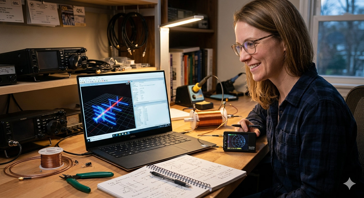
Think of antenna modeling software as a virtual antenna test lab on your computer. Instead of building antennas and going outside to see if they work, you can draw the antenna on your computer and see how it will perform before you even cut any wire.
The software does the real physics calculations. It doesn’t guess. It uses the same math that engineers use to design cell phone towers and radar systems.
The most popular programs for hams use something called “NEC” (which stands for Numerical Electromagnetics Code). This was created by scientists at Lawrence Livermore Lab back in the 1970s. It’s free and very accurate.
What can antenna software actually tell you?
| What it shows | Why you care | Example programs |
|---|---|---|
| How much resistance and reactance at the feedpoint | Tells you if you need a 49:1 transformer or a 9:1 or just 1:1 | 4nec2, EZNEC |
| Where the signal is radiating (the pattern) | Shows if your antenna is throwing power at the sky or into your neighbor’s house | MMANA-GAL |
| What angle is the signal strongest | A vertical antenna on the ground shoots at 25 degrees up. On a balcony it shoots at 45 degrees, which is worse for DX | AN-SOF |
| Where the current is flowing on the antenna | Shows where you might need to add coils or where problems will happen | AutoEZ, EZNEC |
| How much power is getting lost in the wire and ground | Thin wire loses energy. Bad ground loses energy. The software shows exactly how much | EZNEC Pro |
| Where are the dangerous RF hot spots around the antenna | Shows if you’re going to get RF shock or mess up your computer in the shack | FEKO |
Why an antenna analyzer (like NanoVNA) is not enough
A NanoVNA is great. It’s cheap and portable. But it only tells you ONE thing: the impedance at your radio.
Here’s the problem: many different antennas can have the same SWR reading, but completely different performance.
Example: Two antennas might both show 1.5:1 SWR on the NanoVNA. But one works great for Europe, and the other wastes half the power in the ground. You can’t tell which is which just by looking at the meter.
You need to see:
- The radiation pattern (is it going up, or sideways, or into the ground?)
- The efficiency (how much power is actually being radiated vs wasted as heat?)
- The current distribution (where is the power flowing on the antenna?)
The NanoVNA can’t show you any of that.
Common mistakes beginners make with antenna modelling software
Using “perfect ground.” If you tell the software “assume perfect ground,” it will predict your 40m vertical will work great. Then you build it, and it doesn’t. Why? Because your actual ground is terrible. The software needs to know if you have salt marsh, sandy soil, clay, or rocky ground. Each one is different. There are maps that show what kind of ground you have.
Forgetting about the coax cable. The cable coming from your radio to the antenna matters. If you ignore it in the model, you’ll miss common-mode current problems (that’s RF on the outside of the shield, which causes feedback and RFI). Model the coax as part of the antenna in your software.
Not using enough segments. The computer breaks your antenna into small pieces to do the math. If you use too few pieces, the computer gets the wrong answer. Use at least 10 pieces for every half-wavelength of antenna. A 40m dipole needs at least 20 pieces, not 5.
Part 2: Measuring the real antenna outside
Okay, so you modeled your antenna on the computer. Now you need to build it and measure if it actually works like the computer said.
But here’s the problem: your backyard is messy. There are trees, houses, metal gutters, and power lines everywhere. All of that stuff reflects radio waves and messes up your measurements.
To get an accurate measurement, professionals use something called an “anechoic chamber” (pronounced an-eh-KOH-ik). It’s a room lined with special foam that absorbs radio waves. No reflections. No mess.
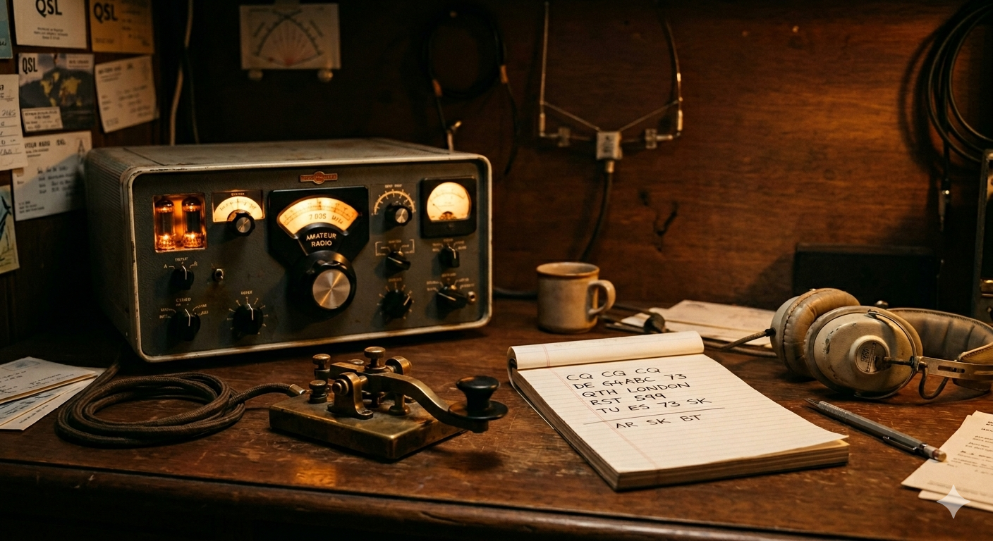
Why “got a 59 report from Japan” is NOT real data
When someone says “I got a 59 from Japan, my antenna must be great,” that’s not real measurement data. Here’s why:
- Radio propagation changes by 20 dB every 10 minutes (that’s a massive difference)
- One day skip is open, next day it’s closed
- The other station might have a really good receiver
- They might have been on a hilltop
- They might have had 1500 watts and a huge antenna
Real antenna data comes from systems that measure consistently. The Reverse Beacon Network and WSPRnet are better. You can turn your antenna 360 degrees, wait for measurements from 10+ different receiving stations, and then plot a real pattern. That’s real data.
Part 3: Why cutting wire randomly doesn’t work
Problem 1: You find a “bad good” solution
SWR is just one number. But many completely different antennas can have the same SWR.
Example: You have a 40m end-fed antenna with a short counterpoise (return wire). You measure 1.3:1 SWR. Good enough, right? So you leave it.
But then you add 2 meters of counterpoise wire. Now the SWR goes UP to 1.8:1. Worse!
But, if you measure with a power meter, the antenna is now 70% efficient instead of 40%. That’s DOUBLE the power going out!
The SWR meter made the first antenna look “good” when it was actually wasting your power. You just can’t see it.
The computer model shows you both: SWR AND efficiency.
Problem 2: You can’t see what changes cause
Let’s say you add a coil (inductor) to load your antenna for a lower frequency.
The coil makes the frequency lower. Good.
But the coil also does three bad things:
- It makes the bandwidth narrower (suddenly 7.2 MHz is 5:1 SWR instead of 1:1)
- It adds resistance that wastes 20% of your power as heat in the coil
- It changes where the current flows on the antenna, and now RF gets back to your radio
If you just try and guess, you only see the SWR change. You don’t see these other problems.
The computer model shows all three things at once.
Problem 3: Your antenna only works at YOUR house
You built a 20m vertical at Field Day on salt marsh. It worked great. S9+ to Europe. Beautiful.
You bring it home to your sandy backyard. Now it’s only S5. Terrible!
Why? Salt marsh is conductive (RF travels through it easily). Sandy soil is not conductive (RF gets absorbed).
If you modeled the antenna, you would have changed “ground type” from “salt marsh” to “sandy soil” and the software would have predicted the 6 dB loss before you even built it. Then you could have added more radials (ground wires) or changed the design.
Part 4: The right way to design an antenna (what the pros do)
Step 1: Write down what you actually want
Don’t just say “I want a 40m antenna.” Be specific.
Write this down: “40m and 20m bands. Must fit in a 15 meter lot. I want to work Europe (not local). I can spend $100. I don’t want to use a tuner.”
Now you have a CONSTRAINT. The computer can help you pick from designs that fit those constraints.
Step 2: Test 5 different designs on the computer
Try these:
- End-fed half-wave with a counterpoise
- Two dipoles with a switch
- Full-wave loop
- Trapped vertical
- Long-wire antenna
Model each one. Look at the gain at 10 degrees up (that’s good for DX). Look at the SWR. Look at the wire loss. Pick the best one.
Step 3: Measure your materials and use exact values
Don’t say “about 20 meters of wire.” Measure it. Be exact.
If your software model says use #14 wire, use #14 wire. If it says use #12, use #12. The thickness matters.
If you add plastic insulators, they have capacitance. Even a tiny insulator shifts frequency by 30 kHz. Model that.
Step 4: Measure the real antenna with a NanoVNA
Get a NanoVNA. Put it at the feedpoint of the antenna. Measure the impedance and SWR at your frequency.
Write down the numbers. Take pictures. You’re building a data file.
Step 5: If the measurement doesn’t match the model, fix the model
Computer said: resonant at 7.050 MHz. You measured: resonant at 6.900 MHz.
The difference is about 150 kHz. Why?
Probably the soil is different than what you modeled. Or the velocity factor of the coax is different. Adjust the model until it matches your measurement. Now the model is trustworthy for everything else.
Step 6: Save everything and share it
Save the antenna model file (.nec). Save the NanoVNA measurement (.s1p file). Post it to your club website or radio board.
Now other hams can build the exact same antenna instead of guessing. That’s how knowledge grows.
Part 5: What you need to buy (total: ~$150)
Software (FREE):
- 4nec2 – The best free antenna modeling program. Works great. https://www.qsl.net/4nec2/
- MMANA-GAL – Free, very fast, especially good for beams (Yagis). http://gal-ana.de/basicmm/en/
- SimNEC – Combines antenna design with impedance matching visualization.
Hardware (~$150):
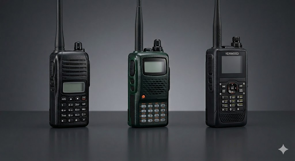
- NanoVNA-H4 ($100-120) – This is a small box that measures antenna impedance. You can use it at home and portable. Works from 10 kHz to 1.5 GHz. This covers everything from 160m ham radio to UHF. Get this one.
- RF current clamp meter (optional, $30-40) – A tool that clips around coax to see if there’s unwanted current. Helps find RFI problems.
- TinySA Ultra (optional, $50-60) – A small spectrum analyzer. Helps you see if your antenna is picking up noise.
For measuring antenna patterns (optional, $0-300):
- Free: Use WSPR. It’s a weak-signal mode. Turn on your antenna, let it transmit for 24 hours while you rotate it every 2 hours. Dozens of receiving stations around the world will report how loud you are at different angles. Plot it. You have a real pattern.
- $300: Buy a cheap drone with a small RF probe. Fly it around your antenna and measure the field strength at different distances and angles.
Part 6: Real example: fixing a 40m end-fed antenna
This is based on real measurements.
What a beginner would do (guess method):
“Okay, I’ll cut 20.1 meters of wire. Use a big transformer (49:1 ratio). Add 2 meters of counterpoise. Let me check the SWR… 1.8 at 7.050 MHz. That’s close enough. Seems to work.”
Result: Antenna radiates okay, but you never know if it’s good.
What a smart builder does (model method):
Model it first:
- Software shows: 20.1m is resonant at 7.200 MHz (not 7.050)
- 30% of your power is lost in the ground (bad!)
- 5 amps of unwanted current on the coax at 100 watts (you’ll get RF in the shack)
Change the design:
- Shorten wire to 19.4 meters
- Add exactly 2.1 meters of counterpoise (0.05 wavelength)
- Add a choke (special coil) on the coax to stop the unwanted current
Measure it:
- NanoVNA shows 1.2:1 SWR at 7.100 MHz (perfect)
- Real tests: +4 dB better signal to Europe than the guessed version
- No RFI in the shack
Time spent: 2 hours modeling, 1 hour building. Versus 8 hours of cutting and trying.
Reference: AA5TB has a detailed guide at https://www.aa5tb.com/efha.html if you want to learn more about end-fed antennas.
Part 7: Why this actually matters
Guessing feels like “real ham radio.” But here’s the truth:
- Marconi didn’t guess. He calculated.
- Yagi and Uda, who invented the Yagi beam antenna, didn’t guess. They did math.
- The first hams to send signals across the Atlantic in 1921 used wave equations and slide rules.
You have a laptop. You can do better than they did.
The process is simple:
- Model it on the computer (shows what’s theoretically possible)
- Build it using the exact dimensions the model said
- Measure it with a NanoVNA (confirms it matches the model)
- Fix it if something is different (now you understand why)
- Document it so next antenna is easier
One SWR meter is not an antenna lab. But a cheap NanoVNA + free 4nec2 software + a parking lot IS an antenna lab.
Stop accepting “it works okay.” Make it work RIGHT. Better signals. Happier neighbors. Clear spectrum.
Resources and where to find them
Learn antenna modeling:
- 4nec2 official site: https://www.qsl.net/4nec2/
- MMANA-GAL (free antenna software): http://gal-ana.de/basicmm/en/
- AA5TB end-fed antenna guide: https://www.aa5tb.com/efha.html (very detailed, good learning resource)
Professional standards (if you want to dig deep):
- IEEE Standard 149-2021 on how to measure antennas correctly: https://standards.ieee.org/ieee/149/6667/
- ITU soil properties map (useful for ground conductivity): https://www.itu.int/rec/R-REC-P.527
Antenna research data:
- N6LF antenna articles (ground systems, measurements): https://www.antennasbyn6lf.com/
- ARRL antenna book and research: https://home.arrl.org/action/Shop/Products
Real-world antenna data from other hams:
- Reverse Beacon Network (see how you compare to others): https://www.reversebeacon.net/
- WSPRnet (weak signal propagation reports): https://www.wsprnet.org/
Get a NanoVNA:
- Available from many electronics retailers
- Search for “NanoVNA-H4” to get the latest version (10 kHz to 1.5 GHz range)
- Cost: $100-150


Post Comment