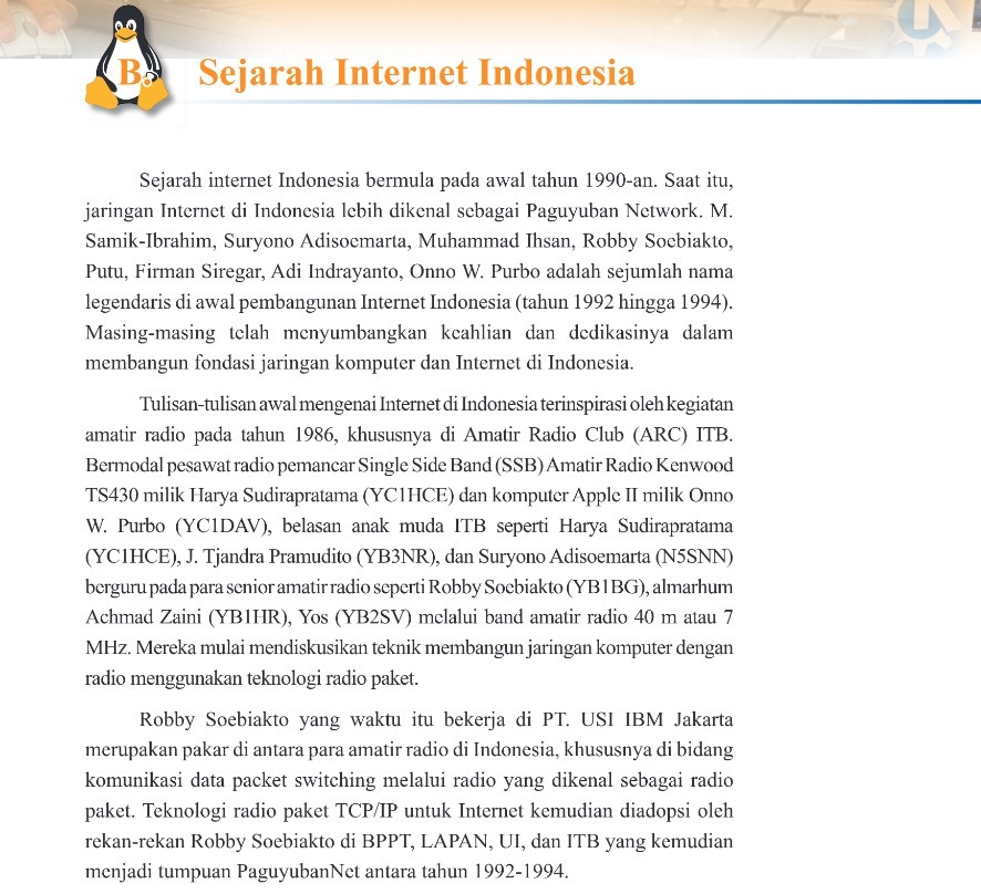
TP-6N: Evolution and Application of a Field Telephone


The TP-6N, a Norwegian-made field telephone, was initially crafted for the Norwegian and Dutch armed forces, known as the TA4881 veldtelefoon by the Dutch. Conceived by Elektrisk Bureau in Billingstad, Norway, it received accolades for design excellence in 1973. Dubbed the “cricket phone” due to its distinct tone, this device gained popularity. Subsequently, the Chinese developed their version, the HDX-1, based on this design.
In 2008, we acquired TP-6N phones from a surplus supplier in the US with the aim of assessing their compatibility with older field phones utilized in search and rescue operations. These phones exhibited remarkable efficacy and reliability, especially in demanding cave environments. This page serves as an informational hub for owners, users, and those interested.
Although portable radios are typically favored for rescue communication, wired telephones present an alternative devoid of radio interference, offering enhanced privacy. Moreover, they operate underground where standard radios falter. Consequently, the military-style field telephone system stands as a prevalent standard for cave rescue communication in North America.


TP-6N Overview:
Bringing significant enhancements over its predecessors, the TP-6N boasts remarkable features:
- Compact and lightweight: Approximately one-third the size and weight of the TA-312/PT field phone, and comparable in weight to the TA-1/PT sound-powered phone.
- Seamless integration: Direct interface with older field phones using standard 2-conductor WD-1A/TT wire or equivalent.
- Enhanced voice clarity: Offers significantly improved voice clarity compared to earlier field phone models.
- Durability: Built to withstand harsh conditions, waterproof, and employs reliable solid-state modular construction with minimal power consumption.
- Intelligent signaling: Incorporates an electronic ringing generator for alerting other phones, accompanied by an indicator light and handset buzzer signaling incoming calls and diagnosing line fault conditions.
- Battery flexibility: Even without batteries, the TP-6N functions as a sound-powered phone over short distances.
- Compact dimensions: Body size approximately 10 x 4 x 2 inches, handset 9 x 3 x 2 inches, satchel 10 x 7 x 2 inches.
- Weight options: Weighs 3 lbs 14 oz including carry satchel and 3 x D cell alkaline batteries, or a total of 3 lbs when utilizing an innovative adapter with 3 x AA batteries.
Built-in Troubleshooting Feature:
- Simple diagnostics: Pressing the call button enables basic diagnosis. Rapid blinking of the red indicator lamp with a faint clicking/chirping tone indicates connection with another TP-6N.
- Signaling limitations: Users connecting TP-6N phones to other models should note potential limitations with the ringer circuit, especially with older phones.
AA Battery Adapter:
- Convenient power option: An AA battery adapter has been designed and produced, offering ease of use with modern batteries.
- Battery recommendations: Suggested batteries include alkaline, lithium, or high-capacity rechargeable nickel-metal hydride cells. Avoid older technology rechargeable AA batteries for rescue use.
- Battery compatibility: Ensure alignment of the spring on the rear cover with the battery contact when installing batteries.
- Battery management: Caution against excessive ringer use to prevent battery depletion, and avoid mixing different battery types.


Line Clips:
Unlike open-sided terminals found on other field phones, the line terminals of the TP-6N are specifically designed to connect to the END of a wire, rather than any point along it.
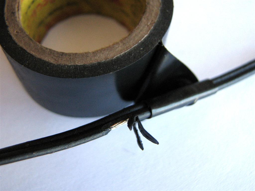
To enable flexible connection anywhere along the phone line, attach a pair of leads with alligator clips to the TP-6N. Crafting these is straightforward using jumper lead sets or 18-gauge twin insulated lamp cord. Begin by stripping away about half an inch of insulation, then twist the wire and solder to prevent fraying. For added reliability, solder and crimp the wires to the clips. Bind the leads together with a short sleeve of heat shrink tubing or simply tie them with a knot.
Store the clips alongside the phone for swift connections. For tapping into military WD-1 phone wire, a simple method involves using a sharp blade to make small cuts and peel away insulation from each conductor. Attach the clips, ensuring contact with the bare wire. While there’s no need to separate the conductors in the middle, take care to prevent the clips from twisting and losing contact. Once disconnected, wrap the wire with insulation tape.


Connecting Multiple Phones:
When linking multiple field phones along a shared line, it’s crucial to connect them in parallel, ensuring both sides of the line are hooked into every phone. This configuration optimizes reliability and functionality, especially in setups utilizing a local-battery system devoid of a central switchboard.
Avoid the temptation to connect TP-6N field phones in series, following the outdated “Platoon Hot Loop” method used in the military. Doing so risks a complete communication blackout if there’s a break in the wire or a single phone failure. Additionally, this method alters the internal resistance of the loop with each added phone, resulting in a reduction in both voice clarity and ringer effectiveness.


Maintenance, Modification, and Technical Data:
The TP-6N manufacturer indicates an “estimated MTBF” (Mean Time Between Failures) of at least 7 years under standard military conditions, though cave rescue demands much more.
Routine maintenance is straightforward: Remove batteries before storage, ensuring the phone is clean and dry inside-out. Inspect the rear cover for proper screw threading and intact seals. Confirm the battery compartment spring and circuit board terminal block are secure and aligned. Check the call button, PTT switch, wire terminals, and handset cable for damage. Test all phones before and after use, prompting users to label any defects they encounter.
The handset cable, a common vulnerability in field phones, warrants attention. While some TP-6N models feature curly cords, most use straight cables, either the older 7mm (1/4 inch) diameter or the newer, more flexible 5mm (3/16 inch). Over time, all cables degrade, particularly the older variants, becoming rigid with outer insulation flaking and inner core deterioration. If an older cable poses issues, replacement is likely preferable to repair.
Damage to newer thin handset cables is usually repairable. For detached ends, carefully guide the cable through the gasket after lubrication with Aquaseal, securing it with a nylon strain relief cord or cable ties. If cut or damaged, create a new gasket seal with rubber splicing tape, soldering old end connectors onto shortened wires and insulating with heat shrink.
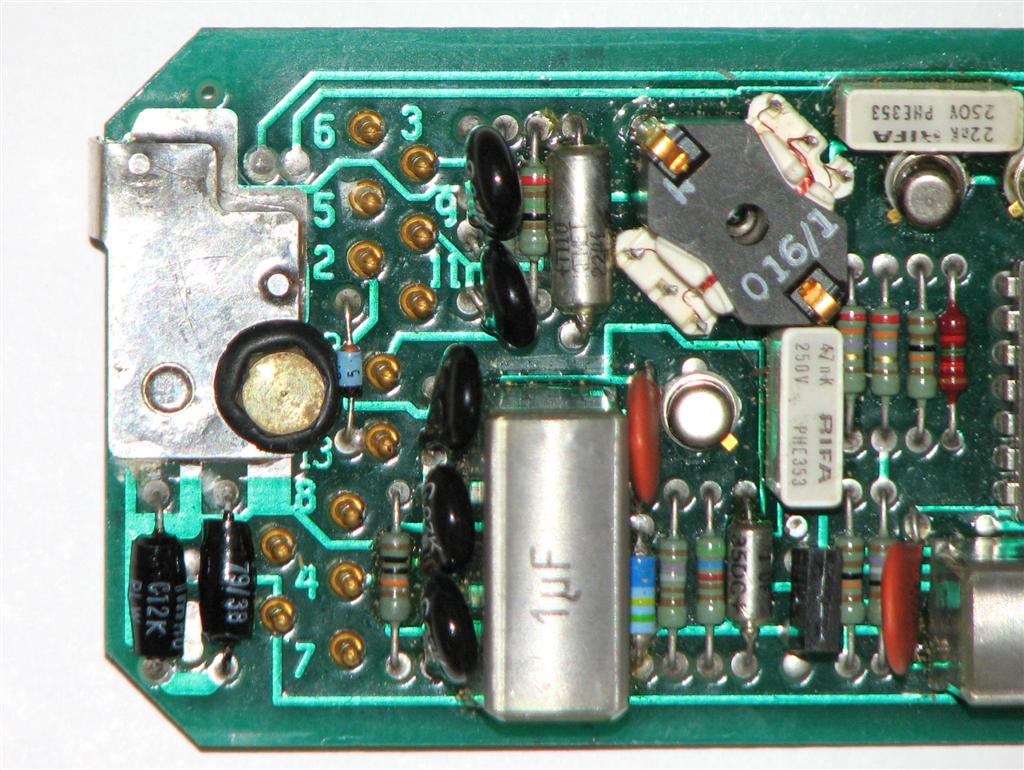
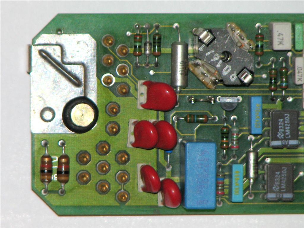
Inside the phone body, wires plug onto pins on the circuit board, prone to loosening or breaking from the call button terminals. Ensure terminals are separate and the call button functions correctly. For other technical issues, utilize a working phone for fault finding, isolating defective parts for replacement or spare usage.


Circuit Board Terminal Connections:
In the Dutch version, TA4881, the circuit board connects to 13 wires. While earlier boards have 13 pins, some later iterations feature 16 pins, with the additional three left unused. Conversely, the Norwegian version, TP-6N-A, has 10 wires connecting directly to 10 pins on the circuit board.
Here’s a clearer representation of the terminal connections:
| Pin | Wire Color | Connected To |
|---|---|---|
| 1 | ORN | Call Button |
| 2 | BRN | Handset |
| 3 | WHT/YEL | Call Button |
| 4 | RED | Handset (via diode block) |
| 5 | BRN | Call Button |
| 6 | YEL | Handset |
| 7 | BLU | Handset |
| 8 | GRN | Call Button |
| 9 | BLK | Handset |
| 10 | YEL | Terminals |
| 11 | BLK | Terminals |
| 12 | RED | Terminals |
| 13 | BLU | Call Button |
This format makes it easier to understand the connections between wires and terminals.
Press-To-Talk Switch Modification:
The standard TP-6N-C handset integrates a combined press-to-talk and press-to-listen switch, requiring users to press the switch to receive voice signals. This can prove counterintuitive and frustrating compared to other field phones.
Originally, the TP-6N-A version utilized a conventional press-to-talk switch, enabling continuous reception of voice signals. However, concerns over communication security arose as the earphone could inadvertently act as a ‘bug,’ picking up nearby conversations when the phone was idle. Consequently, the C-version was swiftly developed, becoming the standard variant.
Fortunately, reverting to the original functionality is straightforward. Modifying the handset switch wiring as illustrated permits continuous reception of voice signals, even without batteries in the phone. Notably, this adjustment imposes no additional current draw on the phone’s batteries.
- Begin by removing the four plastic caps situated at the corners of the earphone. These caps are typically tightly sealed and may pose a challenge to remove. You can attempt to extract them using the point of a knife or a small flat-blade screwdriver. Alternatively, a quicker method involves puncturing the middle of each cap and popping it out.

- Next, unscrew the four screws securing the cover of the earphone and carefully remove it. Take caution as you lift the earphone out, and then turn it over, paying attention to the position of the rubber gasket and O-ring seal.
- Upon inspection, you’ll notice two screw terminals with wires attached, along with a DIAC wired across the terminals and concealed with a sleeve. This setup shields the earphone from alternating current noise. Proceed by unscrewing the terminals and reconnecting the BLUE and BROWN wires together on one side, and the BLACK wire on the other side. Polarity is irrelevant, so the sides can be interchanged. Use a small wrench to securely tighten the terminals after making the new connections.
- With care, reassemble the handset, ensuring that the wires are not pinched and that the gasket is correctly positioned. Align the inner O-ring between the earphone and the cover. If the old plastic caps are intact, replace them. Alternatively, apply hot glue or a similar substance to fill the screw holes, serving as a barrier against dirt and moisture that could lead to corrosion. Should the handset need to be reopened, the material can be easily removed using a small screwdriver.
TP-6N Manufacturer’s Brochure:
This brochure, graciously provided by DSK from Norway, offers detailed information. Click on each page to enlarge the image. The technical data from page 4 is depicted magnified at the bottom.
Field Telephone Pocket Guides (in Dutch):

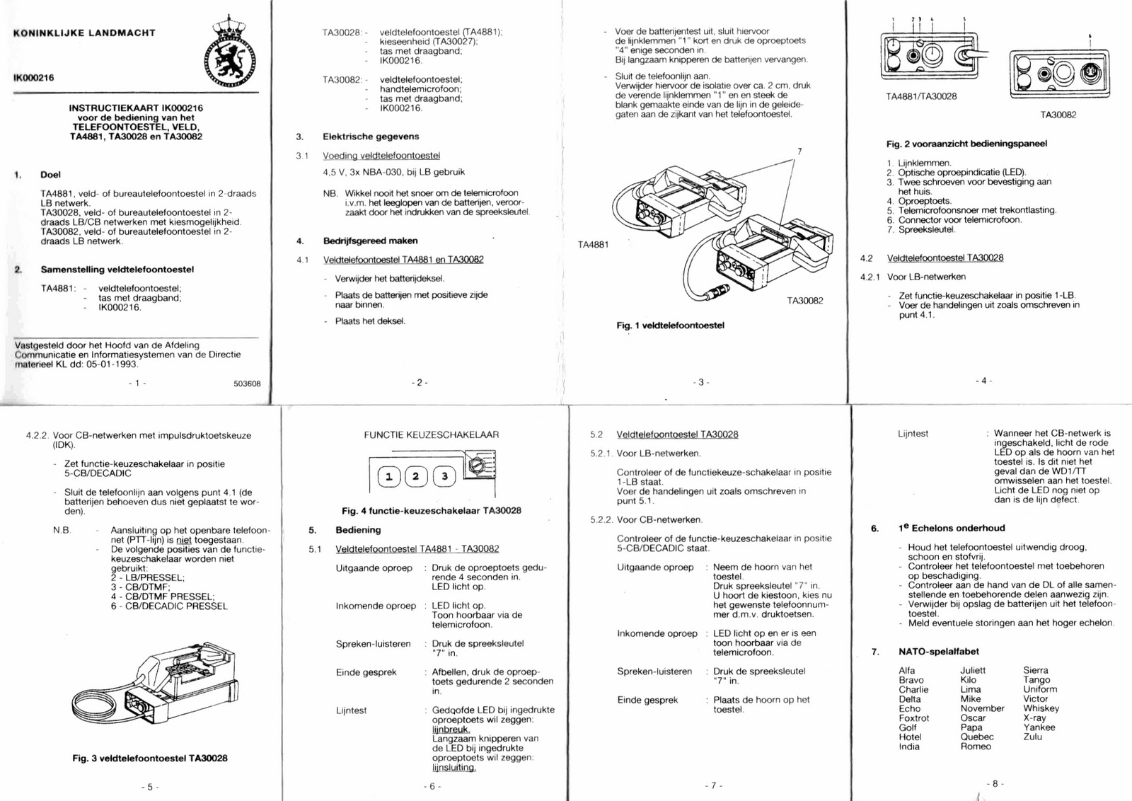
Royal Netherlands Army – Field Telephone TA4881 Instructions:
- General Information
Purpose: Field or office telephone set in a two-wire LB network.
Composition: Field telephone set case with shoulder strap.
Electrical Data: Powered by 4.5 V (3 x NBA030).
Mechanical Data: Telephone set dimensions: 250x190x60mm. Telephone set weight: 16.66 Newton.
- Preparation
- Remove the battery lid (1). Insert the batteries with the positive side facing (+) (2). Replace the lid.
- Battery Test: Connect terminals together (3) and press the call button (5). The call indicator (4) blinks. Replace batteries if the indicator blinks slowly.
- Connect the telephone line: Remove insulation for approximately 2cm. Press down on the terminals (3) and insert the bare ends of the line into the holes on the side of the telephone apparatus.
- Operation
- Outgoing Call: Press the call button for 2 to 3 seconds to light up the call indicator.
- Incoming Call: The call indicator lights up, and a tone is audible in the microphone.
- Speaking/Listening: Press the talk key (6).
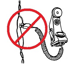
Note: Never wind the cord around the handset as it could drain the batteries.
- Line Test
- Indicator does not light up when the call button is pressed = line break.
- Indicator blinks slowly when the call button is pressed = line short.
- First Echelon Maintenance
- Store the telephone apparatus dry, clean, and dust-free.
- Account for damages to the telephone apparatus.
- Verify all components and parts with the DL.
- Determine the operations for the telephone apparatus.
- Remove batteries when not in use.
TP-6N Description from Jane’s Military Communications:
The TP-6N field telephone set was developed in cooperation with the Norwegian armed forces. It is a lightweight, waterproof electronic unit available with push-button or rotary dial options. Consisting of an olive-green H-67N-type handset and case with printed circuit board and batteries. The handset is molded in reinforced plastic, and the case is aluminum alloy.
The handset includes a microphone, earphone, and press-to-talk switch, with an optional belt clip. It is fully compatible with traditional magneto and CB telephone systems.


Post Comment