amateur radio
ham radio
radio amatur
amateur radio, antenna efficiency, antenna grounding, common mode current, counterpoise, eddy current, EMI, ferrite choke, ground conductivity, ground radials, ham radio, ham radio antenna, HF radio, radio interference, RF current, RF ground, RF grounding, RFI, soil conductivity, vertical antenna
9M2PJU
0 Comments
RF Current, Grounding, and Interference: Guide for Amateur Radio Operators
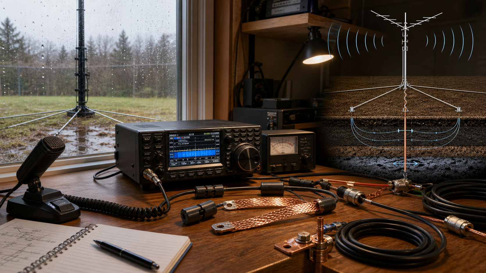
Amateur radio is a hobby built on invisible energy. We launch signals into the air, guide radio-frequency current through feed lines and antennas, and try to receive weak signals from stations hundreds or thousands of kilometers away. Because we work directly with RF energy, we quickly encounter terms that sound simple but are often misunderstood: RF current, eddy current, RFI, EMI, RF ground, counterpoise, ground conductivity, and the basic but important question: is RF AC or DC?
These ideas are not just theory. They affect how clean your transmitted signal is, how noisy your receiver sounds, whether your computer speakers buzz when you transmit, whether your antenna tunes properly, how well a vertical antenna performs, and whether your station behaves safely and predictably. A good amateur radio operator does not need to be an electrical engineer, but understanding these concepts will make you a better troubleshooter and a cleaner operator on the bands.
Is an RF Signal AC or DC?
An RF signal is AC, not DC.
DC, or direct current, flows in one direction only. A battery is the classic example. If you connect a lamp to a battery, current flows from one terminal, through the circuit, and back to the other terminal in one steady direction.
AC, or alternating current, changes direction repeatedly. Household mains power is AC, usually 50 Hz or 60 Hz depending on the country. That means the current reverses direction 50 or 60 times per second.
RF is also AC, but at a much higher frequency. The term RF means radio frequency. In amateur radio, RF signals may range from hundreds of kilohertz to many megahertz, and even into gigahertz for VHF, UHF, and microwave operation. For example, a signal on the 40-meter amateur band around 7 MHz is alternating about seven million cycles per second. A 2-meter FM signal around 145 MHz is alternating about 145 million cycles per second.
This is why RF behaves differently from ordinary DC wiring. At DC, a wire is mostly just a conductor with resistance. At RF, the same wire also has inductance, capacitance, radiation, skin effect, and transmission-line behavior. A piece of wire may become an antenna. A ground lead may stop acting like a ground. A coax shield may carry unwanted current on its outside. A metal object nearby may develop induced current.
So when amateur radio operators talk about “RF current,” they are talking about alternating current at radio frequency. It moves back and forth very rapidly in antenna elements, feed lines, coils, matching networks, and station wiring.
This also explains why antennas work. A changing current creates a changing electromagnetic field. When RF current flows in an antenna, the changing electric and magnetic fields propagate through space as a radio wave. A DC current by itself does not radiate a useful radio signal in the same way because it does not continuously alternate and create a repeating electromagnetic wave.
In simple terms:
- DC flows one way.
- Low-frequency AC reverses direction slowly, such as 50 or 60 times per second.
- RF is high-frequency AC, reversing thousands, millions, or billions of times per second.
For amateur radio, this distinction is important. Many station problems happen because operators think of RF wiring like DC wiring. But RF current does not always follow the path that looks shortest on a diagram. It follows the path of lowest impedance, and impedance at RF includes resistance, inductance, capacitance, frequency, conductor shape, and nearby objects.
That is why good RF practice uses short connections, wide bonding straps, proper coax, common-mode chokes, tuned antennas, radials, counterpoises, and careful layout. At radio frequency, the whole station can become part of the circuit.
Eddy Current
An eddy current is an electric current that circulates inside a conductive material when that material is exposed to a changing magnetic field.
The word “eddy” comes from fluid motion. If you have ever watched water swirl behind a rock in a river, you have seen an eddy. In metal, an eddy current is a similar kind of circulating motion, except the moving thing is electric charge rather than water.
In radio work, changing current produces changing magnetic fields. Alternating current at RF frequencies changes very rapidly, so it can induce currents in nearby conductive objects. These induced currents may form loops inside metal panels, towers, brackets, shields, chassis, tools, roofing, fencing, or poorly bonded station equipment.
Eddy currents are not always bad. In some systems, they are useful. But in amateur radio stations, they are often important because they can cause power loss, heating, detuning, unwanted coupling, or noise problems.
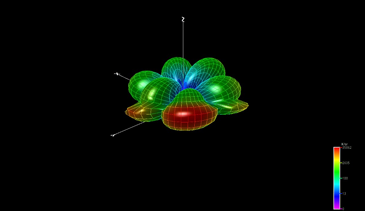
For example, suppose you mount an antenna close to a large metal roof, a steel mast, or a nearby fence. The antenna’s RF field can induce currents in those metal objects. Those currents may absorb some of your transmitted energy and convert it into heat. More importantly, they can change the radiation pattern of your antenna. Your antenna may no longer behave like the textbook diagram says it should.
Eddy currents are also related to shielding. A metal enclosure can block RF partly because RF energy induces currents in the shield, and those currents create fields that oppose the incoming field. That is one reason metal radio cabinets, coax shields, and screened enclosures are useful. However, shielding only works properly when the shield is continuous, well-bonded, and appropriate for the frequency involved.
At high frequencies, another related effect becomes important: skin effect. RF current tends to flow near the surface of a conductor rather than evenly through its entire cross-section. This means conductor shape, surface condition, and bonding quality can matter more at RF than they do at DC or low-frequency AC. A wide copper strap may be a better RF conductor than a long round wire, not because round wire cannot conduct, but because inductance and surface area become important at RF.
For amateur operators, the practical lessons are clear: use good bonding between station equipment, avoid loose metal structures near antennas when possible, keep antenna elements away from large conductive objects unless they are intentionally part of the antenna system, and use proper shielding and grounding practices. At RF, nearby metal is rarely “just sitting there.” It may be participating in your station whether you intended it or not.
RFI: Radio-Frequency Interference
RFI stands for radio-frequency interference. It refers to unwanted RF energy that disrupts the operation of electronic equipment or radio reception.
In amateur radio, RFI usually appears in two ways. First, your transmitter may interfere with nearby electronics. Second, nearby electronics may interfere with your receiver.
When you transmit, your station intentionally produces RF energy. Ideally, that RF energy leaves through the antenna as a clean signal on the intended frequency. In reality, RF can also travel along microphone cables, speaker wires, power leads, USB cables, Ethernet cables, rotator cables, and the outside of coax shields. When that happens, household electronics may act like unintended receivers.
Common symptoms of transmitted RFI include audio speakers buzzing or picking up your voice, computer equipment freezing or disconnecting during transmit, touch lamps turning on or off, alarm systems misbehaving, televisions or monitors showing lines, RF feedback causing distorted transmitted audio, or SWR changing when you touch equipment and cables.
On receive, RFI may come from switching power supplies, LED lamps, solar charge controllers, computers, routers, battery chargers, plasma TVs, motor controllers, or poorly designed consumer electronics. This type of RFI raises your noise floor and makes weak-signal work frustrating.
A key point: RFI is not automatically the fault of the amateur station. Sometimes the ham station is producing excessive RF in the wrong places. Other times, consumer electronics have poor immunity and respond badly to legal RF fields. A skilled operator investigates calmly instead of assuming blame or innocence.
Good RFI troubleshooting begins with identifying the path. Is RF being radiated directly into the affected device? Is it entering through the power line? Through audio cables? Through a long speaker lead? Through the outside of the coax? Once you find the path, you can apply the correct fix.
Common cures include ferrite chokes, better bonding, shorter cables, improved coax routing, common-mode current suppression, balanced antennas, low-pass filters, high-pass filters for TV systems, and replacing noisy power supplies.
Ferrite cores are especially useful. A ferrite choke placed on a cable increases impedance to unwanted RF current flowing on that cable. The correct ferrite material depends on frequency. For HF, mixes such as 31 and 43 are commonly used. For VHF and UHF, other materials may perform better. Multiple turns through a ferrite core often increase choking impedance significantly.
For the transmitting station, common-mode current is one of the biggest RFI troublemakers. This occurs when RF current flows on the outside of a coax shield. Coax is supposed to carry RF inside the cable, with current on the center conductor and inside surface of the shield. But if the antenna system is unbalanced or lacks a proper return path, current can flow on the outside of the shield too. The feed line then becomes part of the antenna, bringing RF back into the shack.
A good common-mode choke at the antenna feed point, and sometimes another near the shack entrance, can greatly reduce RFI.
EMI: Electromagnetic Interference
EMI stands for electromagnetic interference. It is a broader term than RFI. RFI specifically refers to interference at radio frequencies, while EMI includes unwanted electromagnetic energy over a wider frequency range.
In everyday amateur radio conversation, people sometimes use RFI and EMI interchangeably. That is understandable, but there is a useful distinction. RFI is usually RF-specific. EMI may include lower-frequency interference, impulse noise, switching noise, conducted noise on power lines, magnetic-field coupling, and broadband electromagnetic disturbance.
For example, a nearby electric motor with worn brushes may create broadband EMI that you hear as hash or crackling across the HF bands. A switching power supply may generate conducted EMI on the AC line and radiated RFI from its cables. A lightning strike produces a huge electromagnetic pulse that can affect equipment across a very wide range of frequencies.
EMI can couple into radio systems in several ways. Conducted coupling happens when interference travels along wires. Radiated coupling happens when interference is transmitted through space as an electromagnetic field. Capacitive coupling happens through electric fields between nearby conductors. Inductive coupling happens through magnetic fields, where changing current in one conductor induces current in a nearby loop of wire.
In amateur stations, EMI control often involves several layers of defense. Use clean power supplies. Keep antennas away from noisy electronics. Use ferrites on cables. Bond equipment together. Separate RF cables from data and audio cables where practical. Use twisted-pair or shielded cable when appropriate. Eliminate ground loops when they create noise or hum. Maintain good station layout.
One useful habit is to troubleshoot noise by turning things off. If you have a battery-powered receiver, use it to walk around your house. Turn off circuit breakers one at a time and observe whether the noise disappears. Many operators have discovered that their worst “band conditions” were actually caused by a phone charger, LED light, solar inverter, computer monitor, or cheap power supply.
For the responsible amateur, EMI awareness is part of good station engineering. A clean station is not only about having a pure transmitter signal. It is also about keeping unwanted RF out of places where it does not belong and keeping local noise sources from ruining reception.
RF Ground
“Ground” is one of the most confusing words in radio. It can mean several different things depending on context: electrical safety ground, lightning ground, DC ground, earth ground, chassis ground, signal reference, or RF ground. These are related, but they are not identical.
An RF ground is a reference or return system for radio-frequency current.
That sentence is important. At RF, ground is not simply “a rod in the dirt.” A ground rod may be useful for electrical safety and lightning protection, but it may be a poor RF ground, especially on HF. Why? Because RF current sees impedance, not just resistance. A long wire to a ground rod can have significant inductance. At some frequencies, that wire may behave less like a ground and more like an antenna.
For example, a 10-meter wire connected from your tuner to a ground rod may be electrically short at low frequencies but a significant fraction of a wavelength on higher HF bands. Instead of providing a stable RF reference, it may radiate, pick up noise, or create hot spots in the shack.
This is why operators sometimes say there is no perfect ground at RF, only conductors with impedance. That is a slight exaggeration, but it is a helpful mindset.
An RF ground system may be made of radials, copper strap, a metal vehicle body, a ground screen, a counterpoise wire, bonded equipment chassis, or a large conductive surface. What matters is whether it provides a low-impedance path for RF current at the operating frequency.
Consider a quarter-wave vertical antenna. It needs something to work against. The vertical element is only part of the antenna system. The missing part is the return path, often provided by ground radials. If the radial system is poor, ground losses increase. The antenna may still tune, but much of your transmitter power may warm the soil instead of radiating efficiently.
For a base station, an RF ground is often combined with a station bonding system. Equipment chassis should be bonded together with short, wide conductors where possible. Wide copper strap is better than long thin wire for RF because it has lower inductance. The station ground should also be bonded to the building electrical safety ground according to applicable electrical codes. Separate unbonded grounds can create dangerous voltage differences during faults or lightning events.
For portable operation, “RF ground” may be very different. If you operate QRP with an end-fed wire, your counterpoise, coax shield, radio chassis, and even your body may become part of the RF return system. That is why some portable antennas behave differently depending on whether the coax is lying on the ground, hanging in the air, connected to a tuner, or touched by the operator.
If your radio gives you RF burns, your audio is distorted, your tuner behaves strangely, or your SWR changes when you move cables, you may not have a good RF return system.
Ground or Soil Conductivity
Ground conductivity describes how easily electric current can flow through the soil. In amateur radio, this matters because the earth around an antenna can become part of the RF system, especially for vertical antennas, low antennas, receiving antennas, and ground-mounted installations.
Soil is not a perfect conductor. Its conductivity depends on moisture, mineral content, salt content, temperature, and composition. Wet, salty soil usually conducts much better than dry sand or rocky ground. Clay often performs better than dry gravel. Coastal areas and marshy land can be excellent for certain antennas because salty or moist ground reduces ground loss. Dry inland soil may be much less efficient.
For HF operators, ground conductivity has two major effects: antenna efficiency and radiation pattern.
A ground-mounted vertical antenna depends heavily on its ground system. The vertical radiator carries RF current, but the return current must flow somewhere. If the soil is lossy and the radial system is poor, part of your transmitter power is dissipated as heat in the ground. The antenna may still show a low SWR, but less power is being radiated. This is one of the classic traps in antenna work: a good match does not always mean a good signal.
Good ground conductivity can improve low-angle radiation from vertical antennas, which is useful for DX. Poor ground conductivity can increase losses and reduce the strength of the radiated signal. Over seawater, vertical antennas can perform extremely well because saltwater is highly conductive compared with most soil. This is one reason beach portable stations sometimes produce surprisingly strong signals with simple antennas.
However, most amateur operators cannot choose perfect soil. The solution is to build a better RF ground system. Radials, ground screens, and counterpoise wires help provide a controlled return path for RF current. For a ground-mounted vertical, adding more radials usually reduces ground loss. The radials do not need to be buried deeply; in many installations, they are laid on the ground or placed just below the surface. Over time, grass and soil may cover them naturally.
The number and length of radials depend on the antenna, band, available space, and installation style. A few short radials are usually better than none. Many radials are usually better than a few. For serious HF vertical installations, operators often use dozens of radials. For portable work, four to sixteen temporary radials may provide a practical balance between performance and setup time.
Soil conductivity also affects receiving. Poor local ground and nearby noise sources can increase the noise picked up by some antennas. Beverage antennas, receive loops, and low-noise receiving systems are influenced by ground characteristics, though not always in the same way as transmitting antennas.
It is also important to separate soil conductivity from electrical safety grounding. A ground rod driven into moist soil may have a lower resistance to earth than one in dry soil, but that does not automatically make it a good RF ground for HF. A ground rod can help with safety and lightning protection, but for RF performance, a radial or counterpoise system is usually more important.
Seasonal changes can matter too. After heavy rain, soil conductivity may improve. During a dry season, ground losses may increase. Frozen or very dry soil can behave differently from wet soil. If your vertical antenna seems to perform differently throughout the year, the changing condition of the ground may be one reason.
For amateur radio practice, remember these points:
- Wet, mineral-rich, or salty soil generally conducts better than dry sand, gravel, or rock.
- Good soil can improve vertical antenna performance, especially for low-angle radiation.
- Poor soil increases ground loss unless you provide radials or a counterpoise.
- A good SWR does not prove that the soil or ground system is efficient.
- Ground rods are not substitutes for radials in most HF vertical antenna systems.
- Portable operation near seawater can produce excellent results with simple vertical antennas.
Ground conductivity is one of the hidden factors in station performance. Two operators may use similar radios and antennas, but the one with better soil, better radials, or a better counterpoise may put out a much stronger signal.
Counterpoise
A counterpoise is a conductor or system of conductors used as an artificial RF return path for an antenna.
In simpler words, it is something the antenna works against.
Many antennas require two sides. A dipole has two arms. Current flows in one side and returns through the other. A vertical monopole, however, often has one obvious radiating element and a less obvious return system. That return system may be earth, radials, a vehicle body, a metal roof, or a counterpoise.
A counterpoise is especially common with end-fed antennas, random wires, portable verticals, and compact HF antennas. Without a counterpoise, the antenna system will find some other return path. Often that means the outside of the coax shield, the radio chassis, microphone cable, power cable, or operator. This can lead to RFI, unstable tuning, RF in the shack, and poor efficiency.
A counterpoise does not always need to be connected to earth. This is a common misconception. For RF purposes, a wire above ground can work very well as a counterpoise. Elevated radials for a vertical antenna are a form of counterpoise. The key is that the conductor provides a suitable path for RF current.
How long should a counterpoise be? That depends on the antenna and frequency. A common starting point is around a quarter wavelength for the band of operation, but practical systems vary. End-fed half-wave antennas may use a short counterpoise, the coax shield, or both, depending on transformer design and installation. Random-wire antennas often benefit from one or more counterpoise wires cut to non-resonant or band-appropriate lengths.
For a portable HF vertical, a few radials laid on the ground can make a large difference. More radials usually improve efficiency, especially when ground-mounted. A single counterpoise may allow the antenna to tune, but it may not be very efficient. Four, eight, sixteen, or more radials can reduce ground losses.
There is a difference between tuning and efficiency. An antenna tuner can make the radio happy by presenting a 50-ohm load, but it cannot magically make a poor RF return system efficient. A lossy antenna system can show a good SWR because the losses make it easier to match. A dummy load also has a good SWR, but it is not a useful antenna.
Counterpoise placement matters. A counterpoise wire running through the shack may create RF hot spots and interference. If possible, keep counterpoise conductors outside and away from station equipment. For portable operation, experiment with different lengths and layouts. Sometimes moving one wire a meter or two can noticeably change tuning or reduce RF feedback.
In vehicle-mounted HF operation, the vehicle body often acts as the counterpoise. This is why bonding matters. Doors, hood, trunk, exhaust, body panels, and frame sections may not be well connected at RF. Bonding straps can improve the RF continuity of the vehicle and improve antenna performance.
How These Concepts Work Together
These ideas are deeply connected.
RF is high-frequency AC. Because it alternates so rapidly, it creates changing electric and magnetic fields. Those changing fields allow antennas to radiate, but they can also induce eddy currents in nearby metal, couple into unwanted cables, and cause interference.
Ground and soil conductivity affect how much RF energy is lost near the antenna, especially with vertical antennas. A poor ground system can force RF current into feed lines, station equipment, or lossy soil. A better radial or counterpoise system gives RF current a more useful path and improves efficiency.
A poor counterpoise can cause common-mode current on coax. Common-mode current can bring RF into the shack. RF in the shack can cause RFI to computers, speakers, and other devices. Nearby metal can develop eddy currents that detune antennas or absorb energy. Poor bonding and grounding can worsen EMI problems by giving unwanted currents inconvenient paths through station equipment.
A good station is not just a radio connected to an antenna. It is a complete RF system. The transmitter, feed line, antenna, ground, soil, counterpoise, nearby conductors, station wiring, and house electronics all interact.
Here is a practical example. An operator installs an end-fed wire antenna and connects it directly to a tuner in the shack. The antenna tunes on several bands, but when transmitting on 40 meters, the computer mouse stops working and the microphone audio becomes distorted. The operator adds a ground rod outside the window with a long wire to the tuner. The problem improves slightly on one band but gets worse on another.
What is happening? The antenna lacks a controlled RF return path. The station cables and ground wire are becoming part of the antenna. The long ground lead has significant RF impedance and may be resonant on some bands. RF current is flowing where it should not.
Better solutions might include adding a proper counterpoise outside, using a common-mode choke, moving the matching unit closer to the antenna feed point, improving station bonding, and keeping RF current outside the shack.
Another example: a vertical antenna has a good SWR but performs poorly. The operator has only one short ground rod at the base. The antenna tunes, but reports are weak. In this case, the missing ingredient is likely an effective radial or counterpoise system. The ground rod does not replace radials. If the soil is dry or rocky, the problem becomes even worse. Adding a proper radial field may dramatically improve performance.
Practical Advice for Amateur Radio Operators
First, think in terms of current paths. RF current must flow in complete circuits. If you do not provide a good path, RF will find one.
Second, do not treat a ground rod as a magic RF solution. Ground rods are important for safety and lightning protection, but they are not automatically good RF grounds. For antenna performance, radials and counterpoise systems often matter more.
Third, pay attention to the soil under and around your antenna. Wet or salty ground may help. Dry, sandy, rocky, or poor soil may require more radials or a better counterpoise system.
Fourth, use common-mode chokes wisely. A choke at the feed point of an unbalanced antenna can prevent the coax from becoming part of the antenna. Another choke near the shack entrance can help keep unwanted RF outside.
Fifth, bond your station equipment. Use short, wide conductors where practical. Avoid long, thin ground leads for RF bonding.
Sixth, separate functions in your mind. Electrical safety grounding protects people from fault current. Lightning grounding manages surge energy. RF grounding provides a return or reference for RF current. These systems should be coordinated, but they are not the same thing.
Seventh, track down noise sources methodically. Use a portable receiver, turn off circuits, test power supplies, and listen across bands. Many EMI problems can be found with patient troubleshooting.
Eighth, remember that SWR is not the whole story. A low SWR does not prove that an antenna is efficient, quiet, or properly installed. It only means the transmitter sees an acceptable impedance.
Finally, experiment. Amateur radio rewards careful experimentation. Add radials and compare reports. Install a choke and observe whether RFI decreases. Move a counterpoise and watch the tuner behavior. Bond a vehicle panel and check signal strength. Try portable operation near seawater if you have the chance. Keep notes. The station itself will teach you.
Conclusion
RF current, eddy current, RFI, EMI, RF ground, ground conductivity, and counterpoise are not isolated textbook terms. They describe real behavior that every amateur radio operator eventually faces.
An RF signal is high-frequency AC, not DC. Eddy currents remind us that nearby metal interacts with changing RF fields. RFI is unwanted radio-frequency energy causing trouble. EMI is the broader family of electromagnetic interference that can disturb our stations or be produced by them. RF ground is not simply dirt under the station, but a low-impedance RF return or reference system. Ground conductivity affects how much RF energy is lost or supported by the earth around the antenna. A counterpoise is an intentional conductor system that gives an antenna something effective to work against.
When these concepts are understood, station problems become less mysterious. The buzzing speaker, unstable tuner, noisy receiver, hot microphone, poor vertical performance, seasonal changes in antenna behavior, and unpredictable end-fed wire all begin to make sense.
A well-built amateur radio station does not happen accidentally. It comes from respecting RF current, controlling where it flows, understanding the ground beneath the antenna, and giving RF energy better paths than the ones it would choose on its own. That is part of the craft of radio, and it is one of the reasons amateur radio remains such a rewarding technical hobby.

Post Comment