CST Studio Suite: The Complete Guide to 3D Electromagnetic Simulation, Solvers, and Antenna Design
CST Studio Suite: The Complete Guide to 3D Electromagnetic Simulation, Solvers, and Antenna Design
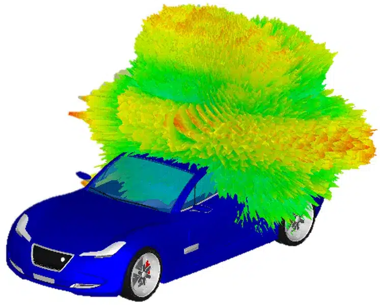
TL;DR: CST Studio Suite (developed by SIMULIA, a Dassault Systèmes brand) is the industry standard 3D electromagnetic (EM) simulation environment for designing, analyzing, and optimizing high-frequency RF components, antennas, radar sensors, filters, and complex cable-chassis assemblies. Unlike single-solver tools, CST integrates multiple numerical engines into one native interface: the Finite Integration Technique (FIT) transient solver for broadband analysis, the Finite Element Method (FEM) frequency domain solver for high-Q structures, the Multilevel Fast Multipole Method (MLFMM) for electrically large platforms, and Asymptotic Ray Tracing (SBR) for installed antenna performance. Engineers and hobbyists can explore electromagnetic design through the free CST Studio Suite Learning Edition.
+---------------------------------------------------------------------------------------------------+
|                                  CST STUDIO SUITE SYSTEM TOPOLOGY                                 |
+---------------------------------------------------------------------------------------------------+
|                                                                                                   |
|   +-------------------------------------------------------------------------------------------+   |
|   |                        NATIVE CAD MODELER & MULTI-FORMAT IMPORTER                         |   |
|   |   • Parasolid Kernel (3D ACIS, STEP, IGES) • PCB Layouts (ODB++, Gerber, IPC-2581)        |   |
|   |   • Cable Harnesses (KBL, NASTRAN)         • Antenna Magus & Array Synthesis Wizard       |   |
|   +-------------------------------------------------------------------------------------------+   |
|                                                 |                                                 |
|                                                 v                                                 |
|   +-------------------------------------------------------------------------------------------+   |
|   |                        UNIFIED ELECTROMAGNETIC SOLVER ECOSYSTEM                           |   |
|   |                                                                                           |   |
|   |   +--------------------+  +--------------------+  +--------------------+  +-----------+   |   |
|   |   | TIME DOMAIN (FIT)  |  | FREQ DOMAIN (FEM)  |  | INTEGRAL EQ (MoM)  |  | ASYMPTOTIC|   |   |
|   |   | • Transient pulse  |  | • Adaptive tetra   |  | • Surface meshing  |  | • SBR Rays|   |   |
|   |   | • PBA curved cells |  | • Narrowband/high-Q|  | • MLFMM clustering |  | • Huge RCS|   |   |
|   |   | • GPU CUDA speedup |  | • True S-parameters|  | • Vehicles & masts |  | • Platforms|  |   |
|   |   +--------------------+  +--------------------+  +--------------------+  +-----------+   |   |
|   |                                     |                                                     |   |
|   |                   +-----------------+-----------------+                                   |   |
|   |                   |                                   |                                   |   |
|   |                   v                                   v                                   |   |
|   |   +-------------------------------+   +-------------------------------+                   |   |
|   |   |   EIGENMODE & PARTICLE 3D     |   |   HYBRID SOLVER COUPLING      |                   |   |
|   |   |   • Cavity filters & slow-wave|   |   • Source nearfield → MLFMM  |                   |   |
|   |   |   • TWTs, klystrons, guns     |   |   • Cable harness → 3D box    |                   |   |
|   |   +-------------------------------+   +-------------------------------+                   |   |
|   +-------------------------------------------------------------------------------------------+   |
|                                                 |                                                 |
|                                                 v                                                 |
|   +-------------------------------------------------------------------------------------------+   |
|   |                         POST-PROCESSING, OPTIMIZATION & SYSTEM CO-DESIGN                  |   |
|   |   • 3D Farfield Gain / Realized Gain / Axial Ratio  • S-Parameters / Smith Chart / TDR    |   |
|   |   • Genetic Algorithm & Trust Region Optimization   • BioEM / SAR Human Phantoms          |   |
|   |   • Cable Studio / EMC / EMI Radiated Emissions     • SIMULIA Abaqus Thermal-Stress MODSIM|   |
|   +-------------------------------------------------------------------------------------------+   |
|                                                                                                   |
+---------------------------------------------------------------------------------------------------+
From miniature mmWave antennas embedded inside 5G smartphones to vehicle-mounted VHF/UHF whip antennas, aerospace radar installations, and high-frequency microwave feedhorns for amateur radio dish stations, designing effective RF hardware requires computational electromagnetics. Physical prototyping at gigahertz frequencies is expensive and time-consuming. A minor trace misalignment or enclosure resonance can degrade radiation efficiency or cause electromagnetic interference (EMI).
CST Studio Suite provides computational electromagnetic field simulation across the entire radio frequency spectrum. It solves Maxwell’s equations directly in three dimensions, enabling engineers and radio experimenters to build virtual prototypes, inspect electric and magnetic nearfields, calculate 3D radiation patterns, and optimize matching circuits before cutting metal or ordering circuit boards.
What Is CST Studio Suite?
CST Studio Suite is a high-performance 3D electromagnetic analysis and multiphysics simulation software suite developed by SIMULIA (Dassault Systèmes) that provides a unified environment of time-domain, frequency-domain, integral-equation, asymptotic, and circuit solvers for designing RF components, antennas, filters, and electronic systems.
Originally created by Computer Simulation Technology (CST) in Darmstadt, Germany, the software earned international recognition through its proprietary implementation of the Finite Integration Technique (FIT). In 2016, Dassault Systèmes acquired CST and integrated the platform into its SIMULIA brand. Today, CST Studio Suite forms a primary pillar of the 3DEXPERIENCE Modeling and Simulation (MODSIM) portfolio.
The Origins and History of CST
Understanding how CST Studio Suite works requires looking at the computational breakthrough that started it.
In 1977, German physicist Professor Thomas Weiland formulated the Finite Integration Technique (FIT). While classical Finite-Difference Time-Domain (FDTD) discretizes Maxwell’s curl equations in differential form, FIT discretizes the integral form of Maxwell’s equations on a pair of dual, interleaved grids:
FIT Integral Formulation:
∮_∂A E · ds = -d/dt ∬_A B · dA   (Faraday's Law)
∮_∂A H · ds =  ∬_A (J + dD/dt) · dA   (Ampère-Maxwell Law)
∯_∂V B · dA = 0   (Gauss's Law for Magnetism)
∯_∂V D · dA = ∭_V q_v dV   (Gauss's Law for Electricity)
By working directly in integral form, FIT guarantees exact conservation of charge and energy on the discrete mesh grid, preventing artificial energy growth during long transient simulation runs.
+---------------------------------------------------------------------------------------------------+
|                                 CST STUDIO SUITE HISTORICAL TIMELINE                              |
+---------------------------------------------------------------------------------------------------+
|                                                                                                   |
|   1977           1992              1998                 2006             2016           Present   |
|    |              |                 |                    |                |                |      |
|    v              v                 v                    v                v                v      |
|  Prof. Weiland  CST Founded in    CST Microwave        CST Studio       Acquired by    3DEXPERIENCE|
|  formulates     Darmstadt,        Studio launched with Suite unifies    Dassault       SIMULIA    |
|  FIT theory     Germany           FIT & PBA meshing    all studios      Systèmes       MODSIM 2026|
|                                                                                                   |
+---------------------------------------------------------------------------------------------------+
In 1992, CST (Computer Simulation Technology) was founded in Darmstadt to commercialize FIT solvers for particle accelerator cavities and microwave structures. In 1998, CST launched CST Microwave Studio (CST MWS), introducing two features that altered the EM simulation landscape:
1. Perfect Boundary Approximation (PBA): Traditional Cartesian time-domain grids suffered from “staircasing errors” when representing curved metallic boundaries. PBA calculates the exact conformal intersection of curved surfaces within rectangular mesh cells, retaining the speed of hexahedral grids with the geometrical accuracy of conformal meshes.
2. Thin Sheet Technique (TST): TST models extremely thin metallic foils, dielectric sheets, and narrow gaps without requiring an excessively dense mesh.
Over the next decade, CST expanded beyond microwave components by adding dedicated studios: CST EM Studio (low-frequency and static fields), CST Cable Studio (automotive and aerospace cable harnesses), CST PCB Studio (signal and power integrity), and CST Particle Studio (charged particle dynamics in traveling-wave tubes and electron guns). In 2006, these separate tools merged into CST Studio Suite. Following the 2016 acquisition by Dassault Systèmes, CST gained tight integration with SIMULIA Abaqus for thermal and structural multiphysics co-design.
Core Electromagnetic Solvers in CST Studio Suite
No single numerical algorithm is optimal for every electromagnetic structure. A small dielectric filter requires a different mathematical approach than a vehicle-mounted antenna array or a stealth aircraft radar cross section (RCS) calculation. CST Studio Suite addresses this through its Complete Technology solver architecture.
+---------------------------------------------------------------------------------------------------+
|                               CST SOLVER DISCRETIZATION COMPARISON                                |
+---------------------------------------------------------------------------------------------------+
|                                                                                                   |
|   [1] TRANSIENT (FIT)             [2] FREQUENCY DOMAIN (FEM)      [3] INTEGRAL EQUATION (MoM)     |
|   Hexahedral Grid + PBA           Conformal Tetrahedral Mesh      Triangular Surface Mesh         |
|                                                                                                   |
|   +---+---+---+---+               /\    /\    /\                  /\----/\----/\                  |
|   |   | / |   |   |              /  \  /  \  /  \                /  \  /  \  /  \                 |
|   +---/---+---+---+             /____\/____\/____\              /____\/____\/____\                |
|   |  /|   |   |   |             \    /\    /\    /              (Only metal/dielectric surfaces   |
|   +-/-+---+---+---+              \  /  \  /  \  /                are meshed; no open air volume)  |
|   (Dual grid preserves charge)    \/____\/____\/                  O(N log N) scaling with MLFMM   |
|                                                                                                   |
+---------------------------------------------------------------------------------------------------+
1. Transient Time Domain Solver (FIT / TLM)
The Transient Solver is CST’s signature engine. It injects a Gaussian or broadband pulse into the structure and tracks electromagnetic field propagation across time steps.
- Broadband S-Parameters in One Run: By taking the Fourier transform of the input and output time signals, a single transient run calculates the entire frequency response (e.g., 1 MHz to 30 GHz) simultaneously.
- Complex Geometry and Port Matching: The solver handles non-linear materials, complex multi-layer structures, and time-domain reflectometry (TDR) impulse responses.
- Hardware Acceleration: The FIT engine scales across NVIDIA CUDA workstation GPUs and distributed compute clusters, accelerating solve times on dense models.
- Transmission Line Matrix (TLM): An alternative time-domain solver specialized for electromagnetic compatibility (EMC) and shielding enclosure analysis involving complex wire bundles and vents.
2. Frequency Domain Solver (FEM)
The Frequency Domain Solver uses the Finite Element Method (FEM) with adaptive tetrahedral meshing and higher-order basis functions.
- High-Q and Narrowband Precision: Ideal for sharply tuned cavity filters, multiplexers, and dielectric resonators where a time-domain pulse would ring for thousands of cycles before decaying.
- Adaptive Mesh Refinement: Automatically refines tetrahedral elements in regions with steep field gradients until S-parameters converge to a user-defined threshold (e.g., Delta S < 0.01).
- True Port Modes: Solves exact 2D eigenmode patterns across waveguide and transmission line cross-sections for precise port impedance calibration.
3. Integral Equation Solver (MoM & MLFMM)
The Integral Equation (IE) Solver uses the Method of Moments (MoM) combined with the Multilevel Fast Multipole Method (MLFMM).
- Surface Meshing: Unlike FIT and FEM, which require meshing the entire volume of surrounding air, the IE solver meshes only the metallic and dielectric boundaries of the structure.
- Electrically Large Structures: Traditional MoM memory scaling of $O(N^2)$ makes large objects impractical. MLFMM clusters interactions hierarchically, reducing memory and CPU scaling to $O(N \log N)$. This allows engineers to simulate antennas mounted on aircraft, naval vessels, and high-rise towers across hundreds of wavelengths.
4. Asymptotic Solver (Ray Tracing / SBR)
For structures thousands of wavelengths across, even MLFMM becomes computationally heavy. The Asymptotic Solver implements Shooting and Bouncing Rays (SBR) and Physical Optics (PO).
- Massive Platform Placement: Simulates radar cross sections (RCS) and installed radiation patterns on full-scale naval ships, military aircraft, and automotive radar urban scenes.
- Multi-Bounce Ray Tracing: Traces millions of geometric optical rays while calculating diffraction along edges using the Physical Theory of Diffraction (PTD).
5. Eigenmode Solver
The Eigenmode Solver calculates the resonant frequencies and field distributions of closed or periodic lossless and lossy electromagnetic cavities.
- Filter Synthesis and Resonators: Directly extracts unloaded Q-factors and coupling matrices for microwave cavity filters.
- Periodic Bandgaps: Evaluates dispersion diagrams for metamaterials, frequency selective surfaces (FSS), and slow-wave structures in traveling-wave tubes.
Comprehensive Solver Selection Matrix
| Solver Engine | Underlying Method | Discretization Grid | Best Applications | Computational Scaling | GPU Acceleration |
|---|---|---|---|---|---|
| Transient (FIT) | Finite Integration Technique | Hexahedral with PBA/TST | Broadband antennas, connectors, UWB, TDR, arrays | Linear with volume $O(N)$ | Full CUDA acceleration |
| Transient (TLM) | Transmission Line Matrix | Octree Hexahedral | EMC/EMI, enclosure shielding, cable coupling | Linear with volume $O(N)$ | Multi-threading / MPI |
| Frequency Domain | Finite Element Method (FEM) | Adaptive Tetrahedral | High-Q filters, narrowband antennas, small components | Matrix inversion $O(N^{1.5} – N^2)$ | Supported (Direct/Iterative) |
| Integral Equation | MoM / MLFMM | Triangular Surface Mesh | Large reflectors, vehicle antennas, EMC radiation | $O(N \log N)$ with MLFMM | OpenCL / CUDA accelerated |
| Asymptotic | Shooting & Bouncing Rays (SBR) | Surface Triangles / CAD | Aircraft RCS, full-city radar, installed mast arrays | Ray count dependent | GPU Ray Tracing |
| Eigenmode | JDM / AKS Eigenvalue | Tetrahedral / Hexahedral | Cavity filters, accelerator cavities, metamaterials | Matrix eigenvalue solve | Multi-core CPU |
The Antenna Design Workflow in CST Studio Suite
Designing an antenna in CST Studio Suite follows a structured numerical workflow, transforming an initial concept into a production-ready design.
+---------------------------------------------------------------------------------------------------+
|                              ANTENNA DESIGN WORKFLOW IN CST STUDIO                                |
+---------------------------------------------------------------------------------------------------+
|                                                                                                   |
|   +--------------------------+        +--------------------------+        +-------------------+   |
|   | 1. GEOMETRY & SYNTHESIS  |  --->  | 2. PORTS & BOUNDARIES    |  --->  | 3. MESH SETUP     |   |
|   | • Parametric 3D CAD      |        | • Waveguide/Discrete Port|        | • Hex PBA / Tetra |   |
|   | • Antenna Magus template |        | • Open (PML) Add Space   |        | • Local refinement|   |
|   +--------------------------+        +--------------------------+        +-------------------+   |
|                                                                                     |             |
|                                                                                     v             |
|   +--------------------------+        +--------------------------+        +-------------------+   |
|   | 6. FINAL FABRICATION     |  <---  | 5. OPTIMIZATION & TUNING |  <---  | 4. EM SIMULATION  |   |
|   | • Gerber/DXF/STEP export |        | • Genetic / Trust Region |        | • Transient solve |   |
|   | • VNA field verification |        | • Target: Return loss<-20|        | • 3D Farfield calc|   |
|   +--------------------------+        +--------------------------+        +-------------------+   |
|                                                                                                   |
+---------------------------------------------------------------------------------------------------+
Step 1: Parametric Modeling and Antenna Synthesis
You begin by creating the antenna geometry using CST’s native ACIS-based 3D solid modeler or importing CAD files (STEP, IGES, DXF, or Gerber).
Every geometrical dimension (radiator length, substrate thickness, feed offset, ground plane width) is assigned parametric variables (such as L_patch, W_patch, h_sub, feed_x). Modifying a variable updates the entire model automatically.
For rapid initial sizing, CST integrates with Antenna Magus, a database of over 350 validated antenna topologies. You input the target frequency, input impedance, and gain, and Antenna Magus synthesizes a fully parameterized CST model ready for immediate simulation.
Step 2: Material Properties and Substrate Definitions
CST includes a broad library of predefined RF substrates (Rogers RO4003C, RO4350B, RT/duroid 5880, FR-4, PTFE) and conductors (annealed copper, gold, PEC).
For advanced applications, you can define:
- Frequency-dependent dispersion: Models loss tangent ($\tan \delta$) and dielectric permittivity ($\epsilon_r$) variation across multi-octave bandwidths.
- Anisotropic and gyrotropic materials: Ferrites for circulators and isolators with tensor permeability.
- Surface roughness: Hammerstad and Huray models to calculate conductor loss in high-frequency mmWave microstrip lines.
Step 3: Port Configuration and Boundary Conditions
Accurate excitation is critical for realistic results:
- Waveguide Ports: Placed at the edge of the substrate or coaxial boundary. CST calculates the exact 2D transmission line modal fields, characteristic impedance ($Z_0$), and propagation constant ($\beta$), ensuring minimal port reflection.
- Discrete Ports: Lumped element ports or wire ports useful for feeding dipoles, loop antennas, or connecting internal surface-mount matching networks.
- Boundary Conditions: For free-space radiation, boundaries are set to Open (Add Space) using Perfectly Matched Layers (PML) to absorb radiating waves without artificial boundary reflections.
Step 4: Meshing and Simulation Execution
For planar and broadband antennas, the Transient Solver with PBA hexahedral meshing is selected. The mesh generator creates dense cells around feed transitions while maintaining larger cells in open air.
During the run, real-time monitors display the decaying energy curve in decibels. Once internal energy drops below a set threshold (typically -40 dB or -50 dB), the simulation stops, and broadband Fourier post-processing begins.
Energy Monitor Decaying Curve:
 0 dB |==========================\
-10 dB|                           \
-20 dB|                            \--------\
-30 dB|                                      \-------\
-40 dB|                                               \------ [Simulation Converged]
      +--------------------------------------------------------> Time (ns)
Step 5: Post-Processing Results Evaluation
CST generates broad post-processing telemetry:
- S-Parameters ($S_{11}, S_{21}$) and Return Loss: Identifies center resonant frequencies, -10 dB bandwidth, and port coupling.
- Smith Chart: Visualizes complex input impedance across frequency, showing whether the feed is capacitive or inductive.
- 3D Farfield Radiation Patterns: Interactive 3D radiation lobes showing total gain, realized gain (including mismatch losses), directivity, front-to-back ratio, and 3 dB beamwidth.
- Polarization & Axial Ratio: Calculates co-polarization and cross-polarization levels along with axial ratio for circularly polarized helical and patch antennas.
- Surface Currents and E/H Field Animation: 3D vector animations showing RF current flow along metal traces, revealing parasitic resonances or edge diffraction.
+---------------------------------------------------------------------------------------------------+
|                              REPRESENTATIVE 3D FARFIELD POLAR PATTERN                             |
+---------------------------------------------------------------------------------------------------+
|                                                                                                   |
|                                                0° (Main Lobe Gain: +8.5 dBi)                      |
|                                            . - ~ ~ - .                                            |
|                                        . '     / \     ' .                                        |
|                                      /        /   \        \                                      |
|                                     /        /     \        \                                     |
|                                    |        |   •   |        |                                    |
|                      270° (-15 dB) |         \     /         | 90° (-15 dB)                       |
|                                     \         \   /         /                                     |
|                                      \       (  v  )       /                                      |
|                                        . '     \ /     ' .                                        |
|                                            ' - . _ . - '                                          |
|                                               180° (Backlobe: -18 dB)                             |
|                                                                                                   |
+---------------------------------------------------------------------------------------------------+
Step 6: Automatic Optimization
If an antenna resonant frequency is off-target or impedance matching requires improvement, CST provides automated optimization engines:
- Trust Region Framework: High-performance local gradient optimizer for rapid convergence with few solver evaluations.
- Genetic Algorithms & Particle Swarm: Global optimizers that search broad multi-dimensional parameter spaces to find optimal geometry configurations without getting stuck in local minima.
- Yield Analysis: Monte Carlo tolerance analysis that evaluates how manufacturing variations (such as $\pm 5\%$ PCB etching tolerance or substrate thickness variation) affect production yield.
Real-World Applications and Engineering Use Cases
+---------------------------------------------------------------------------------------------------+
|                               CST STUDIO SUITE APPLICATION DOMAINS                                |
+---------------------------------------------------------------------------------------------------+
|                                                                                                   |
|   +-----------------------+   +-----------------------+   +-----------------------+               |
|   | 5G/6G & mmWave Arrays |   | Automotive 77GHz Radar|   | Aerospace & Defense   |               |
|   | • Beam steering       |   | • Bumper radome losses|   | • Aircraft RCS & pod  |               |
|   | • Scan blindness check|   | • Vehicle chassis SBR |   | • Satellite feeds     |               |
|   +-----------------------+   +-----------------------+   +-----------------------+               |
|               |                           |                           |                           |
|               +---------------------------+---------------------------+                           |
|                                           |                                                       |
|                                           v                                                       |
|   +-----------------------+   +-----------------------+   +-----------------------+               |
|   | BioEM & SAR Phantoms  |   | Cable & EMC/EMI       |   | Ham Radio Microwaves  |               |
|   | • Human tissue voxel  |   | • Enclosure shielding |   | • Dish feed horns     |               |
|   | • FCC/ICNIRP safety   |   | • ESD transient strike|   | • Cavity duplexers    |               |
|   +-----------------------+   +-----------------------+   +-----------------------+               |
|                                                                                                   |
+---------------------------------------------------------------------------------------------------+
1. 5G/6G Phased Array Antennas and mmWave Systems
At 28 GHz, 39 GHz, and future sub-terahertz frequencies, path loss demands active phased array antennas with high beamforming gain.
- Unit Cell Periodic Modeling: CST models a single antenna element with periodic boundary conditions to compute Floquet modes, mutual coupling, active reflection coefficients, and scan blindness angles before building the full array.
- Array Wizard: Synthesizes large multi-element planar arrays (e.g., $8 \times 8$ or $16 \times 16$ elements), applying amplitude tapering (Taylor, Chebyshev) to suppress sidelobes and calculating steered beam radiation envelopes.
2. Automotive Radar and Installed Platform Integration
Modern vehicles feature multiple 77 GHz ADAS radar sensors mounted behind decorative plastic bumpers and emblems.
- Radome and Paint Layer Effects: The Transient Solver accurately models multi-layer paint coats, plastic curvature, and metallic flake reflections that introduce boresight angle errors and phase distortions.
- Hybrid Platform Modeling: The radar sensor antenna is solved in high-detail using the Time Domain Solver. Its nearfield radiation is exported as an equivalent source and projected across the entire vehicle body using the Asymptotic (SBR) or MLFMM solver, saving gigabytes of memory.
3. EMC/EMI Compliance and Electrostatic Discharge (ESD)
Failing electromagnetic compatibility testing at an accredited test lab can delay product launches by months.
- Virtual Reverberation and Anechoic Chambers: Engineers build virtual test chambers in CST to simulate radiated emissions from printed circuit boards, high-speed differential pairs (6+ Gbps), and switching power supplies.
- ESD Strike Modeling: Simulates transient current propagation and high-voltage arc discharges from human-body electrostatic models across chassis seams and connector pins, identifying component vulnerability to latch-up or destruction.
4. Bio-Electromagnetics and SAR Analysis
Regulatory agencies (FCC, CE, ICNIRP) enforce strict limits on Specific Absorption Rate (SAR) – the RF energy absorbed by human biological tissue from mobile handsets, smartwatches, and medical implants.
- Voxel Human Models: CST provides anatomically detailed voxel phantoms (such as the CST Bio-Models collection) with frequency-dependent tissue conductivity and permittivity across more than 40 internal organs and muscle layers.
- Automated SAR Calculation: Solves 1g and 10g averaged SAR compliance maps, allowing engineers to position internal phone antennas to minimize body absorption while maximizing free-space radiation efficiency.
5. Amateur Radio & Microwave Experimentation
For radio amateurs, microwave enthusiasts, and experimental builders, CST provides precision analysis for high-performance homebrew designs:
- Parabolic Dish Feedhorns: Optimizing septum feed horns, Kumar feeds, and dual-band patch feeds for amateur satellite, EME (Earth-Moon-Earth / Moonbounce), and microwave bands (1.2 GHz, 2.4 GHz, 5.8 GHz, 10 GHz, 24 GHz, 47 GHz, 122 GHz).
- VHF/UHF Cavity Duplexers: Designing high-Q temperature-compensated helical and coaxial resonator filters for repeater stations with steep notch isolation (>90 dB) and low insertion loss.
- Broadband Log-Periodic and Yagi Arrays: Evaluating boom interaction, element mounting conductivity, and stacking distances for weak-signal DX operation.
Industry Tool Comparison: CST vs HFSS vs Feko vs OpenEMS
| Feature / Metric | CST Studio Suite (SIMULIA) | Ansys HFSS | Altair Feko | OpenEMS (Open Source) |
|---|---|---|---|---|
| Primary Flagship Method | FIT (Finite Integration) / Time Domain | FEM (Finite Element) / Frequency Domain | MoM (Method of Moments) / Integral Eq | FDTD (Finite-Difference Time-Domain) |
| Broadband Simulation Speed | Fastest (Single transient pulse) | Moderate (Interpolating frequency sweep) | Slower for wideband volume structures | Fast (Single FDTD time pulse) |
| High-Q Cavity Filter Accuracy | Excellent (via integrated FEM solver) | Industry Benchmark (Adaptive FEM) | Good (via FEM add-on module) | Poor (FDTD rings excessively) |
| Electrically Large Platforms | Excellent (Integrated MLFMM & SBR) | Excellent (HFSS-IE / SBR+ solver) | Industry Benchmark (MLFMM & PO) | Not feasible (Volume grid limit) |
| Unified Multi-Solver Interface | Native Single GUI (Shared model) | Modular (Separate sub-engines) | Modular interface | Script-based (MATLAB / Octave) |
| Curved Boundary Handling | PBA & TST (No staircasing) | Conformal Tetrahedral Elements | Surface Triangles | Traditional Staircase Mesh |
| Cable Harness & EDA Co-Design | Cable Studio & PCB Studio (Native) | Ansys SIwave / Icepak linking | Cable Modeling tools | Basic manual port definitions |
| Free / Student Version | CST Learning Edition (Free) | Ansys Student (Geometry/node limited) | Altair Student Edition | Free & Open Source (GPLv3) |
CST Studio Suite Learning Edition and System Requirements
To help students, researchers, and engineers learn 3D electromagnetic simulation, Dassault Systèmes offers the free CST Studio Suite Learning Edition.
Learning Edition Scope and Limits
-
- Included Solvers: Provides access to the Transient Time Domain Solver and Frequency Domain Solver.
- Modeling and Analysis: Full access to the 3D solid CAD modeling environment, parameterization, and 3D farfield post-processing engines.
- Mesh and Feature Limitations:
* Mesh cell count is capped to prevent massive commercial-scale simulations (sufficient for dipoles, patch antennas, horn feeds, microstrip filters, and small arrays).
* Advanced specialized studios (such as Cable Studio and Particle Studio) and GPU cluster acceleration require commercial or research academic licenses.
- Educational Purpose: Ideal for university coursework, thesis preparation, and hobbyist antenna prototyping.
Recommended Hardware Specifications
Electromagnetic simulation places heavy demands on workstation hardware:
+---------------------------------------------------------------------------------------------------+
|                               RECOMMENDED HARDWARE ARCHITECTURE                                   |
+---------------------------------------------------------------------------------------------------+
|   • Processor (CPU):      Multi-Core Intel Xeon / Core i7-i9 or AMD Ryzen / EPYC (8 to 32 Cores)  |
|   • Memory (RAM):         64 GB to 128 GB DDR5 with high memory bandwidth (ECC recommended)      |
|   • Storage:              High-speed NVMe PCIe 4.0/5.0 SSD for scratch cache directories          |
|   • Graphics (GPU):       NVIDIA RTX Professional (e.g. RTX 4000/5000/6000 Ada or Tesla)          |
|                           CUDA Compute Capability 7.0+ for hardware acceleration                  |
+---------------------------------------------------------------------------------------------------+
Frequently Asked Questions
What is the difference between CST Studio Suite and CST Microwave Studio?
CST Microwave Studio was the original standalone 3D high-frequency simulation tool launched in 1998. In 2006, it merged with CST’s low-frequency, cable, printed circuit board, and particle simulation tools to create the broad CST Studio Suite.
How does the Finite Integration Technique differ from traditional FEM?
FIT solves Maxwell’s equations in integral form across dual hexahedral grids in the time domain, calculating full broadband frequency response in a single run. FEM solves the differential wave equation frequency-by-frequency on tetrahedral meshes, making it ideal for narrowband, high-Q components.
Can CST Studio Suite perform thermal and structural multiphysics co-simulation?
Yes. CST links electromagnetic RF power losses directly into thermal and structural solvers. Integrated within Dassault Systèmes SIMULIA, it exports dissipated electromagnetic heat distributions to Abaqus for thermal stress and structural deformation analysis.
Is there a free version of CST Studio Suite for students and hobbyists?
Yes. The CST Studio Suite Learning Edition is available free from Dassault Systèmes. It includes the 3D modeler, transient solver, frequency domain solver, and visualization tools with a mesh-cell limit designed for coursework and individual educational learning.
How does hybrid simulation work in CST Studio Suite for large platforms?
Hybrid simulation links multiple solver types in one project. A detailed antenna is solved first in the Time Domain, and its radiated nearfields are transferred as an equivalent source to an Asymptotic (SBR) or MLFMM solver to compute full-platform vehicle or aircraft interactions.
Conclusion
CST Studio Suite remains one of the most capable and versatile 3D electromagnetic simulation suites available to RF, microwave, and antenna engineers. By uniting the speed and broadband efficiency of the Finite Integration Technique with high-precision tetrahedral FEM, surface-based MLFMM, and asymptotic ray tracing, CST handles electromagnetic challenges across every scale.
Whether you’re designing next-generation 5G/6G mmWave phased arrays, verifying automotive radar integration, ensuring EMC regulatory compliance, or prototyping custom microwave feedhorns for amateur radio and satellite experiments, CST Studio Suite provides the virtual prototyping fidelity needed to build high-performance RF hardware with confidence.
73, and happy simulating.
Sources and Further Reading
- Dassault Systèmes SIMULIA CST Studio Suite Official Product Portal: 3ds.com CST Studio Suite
- Dassault Systèmes SIMULIA Electromagnetic Simulation Community: SIMULIA Community
- CST Studio Suite Learning Edition Official Download: Dassault Systèmes Academic Portal
- Weiland, T. (1977): A Discretization Method for the Solution of Maxwell’s Equations for Arbitrary Structures. Electronics and Communications AEU.
- Antenna Magus Official Topology Database: Antenna Magus
- VIAS3D Engineering & Electromagnetic Simulation Resources: VIAS3D Antenna Design
- HamRadio.my Open Source and Technical RF Resources: HamRadio.my
- About 9M2PJU Station Profile and Engineering Projects: 9M2PJU Profile



Post Comment