amateur radio
open source
9M2PJU, amateur radio, ARDF, Arduino, beacon, captive portal, cw, direction finding, DIY electronics, DRA818V, esp32, fox hunting, GPL-3.0, hamradio.my, handheld radio, heltec, hidden transmitter, IARU, LilyGO, microcontroller, morse code, OLED, open source, platformio, PTT, SA818V, TFT, TTGO, UHF, VHF, wifi
9M2PJU
1 Comments
Build an ESP32 Fox Hunt Beacon with 9M2PJU Firmware

There is a particular kind of joy in fox hunting that you do not get from any other corner of amateur radio. You stand in a field with a handheld and a small directional antenna, you turn slowly in a circle, and you listen. Somewhere out there, hidden in the bushes or tucked under a park bench, a small transmitter is calling. Your job is to find it.
It is part sport, part radio theory, and part treasure hunt. Clubs around the world run ARDF, Amateur Radio Direction Finding, events that turn a Sunday morning into a quiet adventure across the countryside. The only thing you need, beyond a receiver and a sense of direction, is the fox itself.
That last part is surprisingly hard to source. Commercial ARDF transmitters are expensive, often locked to one band, and rarely flexible enough for a small club that just wants to run a training night. So I built one, and I open sourced it.
The project is 9M2PJU ESP32 Fox Hunt Beacon, an ESP32 firmware that turns a cheap handheld walkie-talkie into a fully timed, IARU-standard fox hunting beacon. It is free, it is GPL-3.0, and it is looking for contributors.
Last updated: July 2026. Firmware version v1.1.0.
What It Is, in One Breath
The 9M2PJU ESP32 Fox Hunt Beacon is a PlatformIO firmware for common ESP32 development boards. The ESP32 handles all the brains, timing, identification, audio tones, configuration, battery monitoring, and push-to-talk control, and a cheap handheld radio provides the actual RF signal.
You do not need to build a transmitter from scratch. You do not need to worry about spectral purity on a homebrew VHF oscillator. You take a Baofeng or Kenwood-style handheld you already own, wire a small PTT and audio interface to an ESP32, flash the firmware, and you have a fox.
As of v1.1.0, the beacon also speaks the full IARU ARDF standard: 5-fox round-robin timing with automatic slot synchronisation, a continuous MO6 finish-line beacon mode, a WiFi captive-portal web admin for phone configuration, and a live status display on boards with an OLED or TFT screen.
It is built and maintained by 9M2PJU, the same Malaysian amateur behind hamradio.my, and it is offered free for the hobby under the GNU General Public License v3.0 or later.
Why an ESP32 and a Walkie-Talkie?
An ESP32 board is a surprisingly good controller for a fox hunt beacon. It has accurate enough timing for ARDF schedules, low-power sleep modes for long field deployments, Wi-Fi and Bluetooth for configuration, GPIO pins for PTT control, an ADC input for battery sensing, and enough processing power to generate clean CW and audio tones in software.
What an ESP32 does not have is a clean, legal VHF or UHF amateur radio transmitter. That is by design. Instead of fighting the RF side, the firmware lets the ESP32 boss around a handheld radio that is already type-built for amateur FM operation. The handheld produces the RF; the ESP32 produces the brains.
This keeps the project cheap, legal, and easy to test. You can build a working fox from an ESP32 DevKit board you have in a drawer and the handheld you already carry on club nights.
Recommended transmitter approaches supported by the firmware:
- A cheap handheld walkie-talkie controlled through PTT and audio input (the main target).
- An external amateur handheld transceiver, for a cleaner RF path.
- A VHF FM module such as the SA818V or DRA818V for a standalone beacon on 144 MHz.
- A UHF FM module such as the SA818U or DRA818U for 430 MHz.
- Other amateur-band transmitter modules, as long as they meet local rules and spectral purity requirements.
Always follow your local amateur radio regulations, band plans, identification requirements, power limits, and event safety rules.
A Tour of the Firmware
What the Beacon Sends
During each transmit window, the firmware sends:
CALLSIGN in CW → short gap → FOX_ID in CW → steady carrier until TX timer ends
For example, with DEFAULT_CALLSIGN set to 9M2PJU and DEFAULT_FOX_ID set to MOE, the radio sends 9M2PJU MOE in Morse code and then holds a steady carrier until the transmit window closes. This matches the IARU ARDF standard signal format.
If you enable the warble (DEFAULT_WARBLE_ENABLED = 1), it sends the CW ID sequence and then alternates a warble tone between 700 Hz and 900 Hz until the TX timer ends. This is non-standard but useful for training, especially with newcomers who find a warble easier to pick out of the noise than a steady carrier.
ARDF means Amateur Radio Direction Finding. In a typical ARDF event, several hidden transmitters, the “foxes”, take turns transmitting short Morse identifiers so competitors can tell which fox they are hearing. The conventional 2 m / 80 m ARDF identifiers are:
| Fox | CW identifier |
|---|---|
| 1 | MOE |
| 2 | MOI |
| 3 | MOS |
| 4 | MOH |
| 5 | MO5 |
| 6 | MO6 (finish-line beacon, continuous mode) |
For a single training beacon, MOE is a good default. For multi-fox events, program each beacon with a different identifier and let fox sync handle the timing. Keep DEFAULT_CALLSIGN set to the licensed station callsign required by your local identification rules.
How a Cycle Works
The beacon is a timed transmitter controller. On boot it loads saved configuration from flash, waits through an optional startup delay so you have time to hide it, and then enters the beacon schedule loop:
- During the idle window, the transmitter is off and the ESP32 may sleep.
- Before transmission, the ESP32 enables PTT and waits a short guard time.
- The ESP32 generates the programmed audio pattern.
- The transmitter sends the tone, CW ID, or voice/audio sequence.
- The ESP32 releases PTT after a short tail delay.
- Battery voltage is checked and status LEDs are updated.
- The cycle repeats until the beacon is powered off or the battery limit is reached.
With the default IARU settings and fox sync enabled, fox 1 (MOE) starts immediately after power-on, transmits for 60 seconds, stays quiet for 240 seconds, and repeats. The full cycle is 300 seconds (5 minutes). Fox 2 (MOI) gets an automatic 60-second startup delay so it takes the second slot, fox 3 starts at 120 s, fox 4 at 180 s, fox 5 at 240 s. All five beacons share one frequency and take turns in the standard round-robin.
IARU Standard 5-Fox Timing
This is the headline feature of v1.1.0. The firmware now ships with defaults that match the IARU ARDF standard out of the box:
- 60 seconds transmit per fox.
- 240 seconds idle between transmissions.
- 300 seconds (5 minutes) total cycle.
- Steady carrier after the CW ID (warble off by default).
- Fox-slot synchronisation so all five beacons share one frequency.
Fox sync (DEFAULT_FOX_SYNC_ENABLED = 1) auto-derives the startup delay from the fox ID. You do not need to manually set a different startup delay for each beacon, just set the fox ID (MOE, MOI, MOS, MOH, MO5) and the firmware works out which slot in the round-robin this unit owns. Power on all five beacons in any order, and they will sort themselves into the standard sequence.
If you want to run a non-standard event, disable fox sync with set fox_sync off and set your own startup, tx, and idle values per beacon.
Continuous Beacon Mode (MO6 Finish-Line)
For the finish-line beacon, the firmware has a separate continuous beacon mode. Switch to it with set mode beacon (or DEFAULT_BEACON_MODE = 1). In this mode the beacon transmits continuously on its own frequency and re-identifies in CW at a configurable interval (set beacon_id 60 for a CW ID every 60 seconds, for example). This is the MO6 finish-line transmitter that ARDF events run on a separate frequency so competitors can home in on the finish.
Switch back to scheduled fox mode with set mode fox.
Web Admin UI
This is the feature that turns the beacon from a bench project into something you can configure in the field without a laptop.
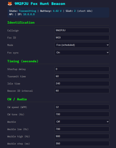
On boot, the ESP32 starts a WiFi access point named FoxBeacon-XXXX (the last four hex digits of the MAC address). Connect to it from a phone or laptop and the captive portal should auto-open the configuration page. If it does not, browse to http://192.168.4.1/.
The web UI lets you:
- View current status (state, battery, fox slot, AP name, IP).
- Edit all settings: callsign, fox ID, mode, fox sync, timing, CW, warble, PTT, battery, WiFi AP on/off, AP auto-off timeout, display eco mode.
- Save settings to flash (same as serial
setcommands). - Trigger a test transmission or PTT test.
- Restore compile-time defaults.
- Reboot the ESP32.
The web UI is served on all boards, every ESP32 has WiFi, so even a bare DevKit gets the admin page. No router or internet connection is needed. The AP has no password by default so it is open for easy field access.
The WiFi AP can be turned on or off from the on-screen settings menu or the web UI itself. When off, the WiFi radio is disabled to save power in the field. The AP also has an auto-off timeout (default 10 minutes): if no client is connected and no web requests are received for the timeout period, the AP shuts down automatically to save power. Set it to 0 to keep the AP on indefinitely. To turn it back on, use the on-screen menu or set wifi_ap on.
On-Screen Status Display
Boards with an OLED or TFT screen show a live status display, a small touch that makes a big difference when you are hiding five beacons in the dark before a hunt.
Startup Screen
On boot, the display shows a startup splash for 3 seconds:
9M2PJU Fox
────────────────
v1.1.0
Starting...
After 3 seconds, it transitions to the status screen.
Status Screen
The status screen shows:
- Callsign and fox ID
- Mode (FOX or BEACON)
- Current state (STARTUP, IDLE, TX, BEACON, LOWBAT)
- Timing (TX and idle seconds)
- Battery voltage (if battery monitoring is enabled)
- Web admin AP IP address (if WiFi AP is enabled)
The display updates once per second.
Settings Menu (On-Screen)
Double-click the button on the status screen to open the settings menu. The menu provides quick on/off toggles for field use without needing a phone or laptop:
| Item | Description |
|---|---|
| WiFi AP | Turn WiFi AP / web admin on or off |
| Warble | Enable/disable warble tone |
| Fox Sync | Enable/disable fox slot synchronisation |
| Battery | Enable/disable battery monitoring |
| Mode | Toggle between FOX and BEACON mode |
| Eco Disp | Enable/disable display eco mode (auto-off after 15 s) |
| Exit | Return to status screen |
Menu navigation:
- Single click: move to next item.
- Double click: toggle selected item.
- Long hold (2 s): exit menu.
- Menu auto-exits after 30 seconds of inactivity.
Full configuration (callsign, fox ID, timing, CW speed, PTT, warble frequencies, battery scale, etc.) is only available through the WiFi web admin UI. The on-screen menu is deliberately limited to on/off toggles for quick field adjustments.
Display Eco Mode
When eco mode is enabled, the display turns off after 15 seconds of inactivity to save power. Any button press wakes the display. This is useful for extended field operations where battery life matters more than constant status visibility.
Supported Display Boards
| Board | Display type | Library |
|---|---|---|
| Heltec WiFi Kit 32 (V1/V2) | OLED SSD1306 128×64 | U8g2 |
| Heltec WiFi Kit 32 V3 | OLED SSD1306 128×64 | U8g2 |
| Heltec WiFi LoRa 32 (V1/V2/V3) | OLED SSD1306 128×64 | U8g2 |
| Heltec Wireless Stick / Stick Lite | OLED SSD1306 128×64 | U8g2 |
| Heltec Wireless Stick Lite V3 | OLED SSD1306 128×64 | U8g2 |
| TTGO LoRa32 V1 | OLED SSD1306 128×64 | U8g2 |
| TTGO LoRa32 V2 | OLED SSD1306 128×64 | U8g2 |
| TTGO LoRa32 V2.1.6 | OLED SSD1306 128×64 | U8g2 |
| TTGO T-Beam | OLED SSD1306 128×64 | U8g2 |
| LilyGO T-Display | TFT ST7789 135×240 | TFT_eSPI |
| LilyGO T-Display S3 | TFT ST7789 170×320 | TFT_eSPI |
| TTGO T-Watch | TFT ST7789 240×240 | TFT_eSPI |
Boards without displays (ESP32 DevKit, ESP32-S3 DevKit, ESP32-C3, TTGO T1, T7, T-OI Plus, T3-S3) still get the web admin UI, they just have no screen.
Firmware Features
The v1.1.0 release covers the full IARU ARDF workflow:
- PlatformIO project for common ESP32 boards, with 31 tested build environments.
- Configurable callsign and fox ID stored in ESP32 flash.
- IARU standard 5-fox timing defaults (60 s TX, 240 s idle, 300 s cycle).
- Fox-slot synchronisation: auto-derive startup delay from fox ID for round-robin.
- Continuous beacon mode (MO6 finish-line transmitter) on a separate frequency.
- CW ID generation using audio tone.
- Optional warble tone for the rest of the transmit window (disabled by default for IARU standard).
- PTT control with guard time before and after audio.
- A
ptt_testcommand for checking radio keying before any audio tests. - Optional battery voltage measurement through a resistor divider.
- Status LED patterns for idle, transmit, and low battery.
- A test button (the boot button on many boards) for an immediate transmission.
- Compile-time configuration file for default beacon behaviour.
- Serial monitor configuration at 115200 baud.
- Web admin UI: WiFi AP with captive portal for phone/laptop configuration.
- On-screen status display for boards with OLED or TFT screens.
- On-screen settings menu with on/off toggles for quick field adjustments.
- Display eco mode to save power on long field deployments.
- WiFi AP auto-off timeout to save power when no client is connected.
Planned features for later phases include Bluetooth serial configuration, deep sleep between transmissions for longer battery life, and multiple fox profiles for event use.
Supported ESP32 Boards
The design works with most 3.3 V ESP32 development boards that expose GPIO pins, ADC input, and USB programming. Recommended starting points are the cheap, common ESP32 DevKit v1, the Espressif ESP32-DevKitC, and the general ESP32-WROOM-32 family.
Beyond the generic boards, the project ships tested PlatformIO environments for a wide range of popular hardware:
- Heltec: WiFi Kit 32 (all three versions), WiFi LoRa 32 (all three versions), Wireless Stick, Wireless Stick Lite, Wireless Stick Lite V3, Wireless Tracker (TFT), Vision Master T190 (TFT), Wireless Paper (E-Ink), Vision Master E213 (E-Ink), Vision Master E290 (E-Ink), and Capsule Sensor V3.
- LilyGO / TTGO: T-Display, T-Display S3, T3-S3, LoRa32 V1/V2/V2.1.6, T-Beam, T-Watch, T1, T7 V1.3/V1.4 Mini32, and T-OI Plus (ESP32-C3).
- Modern Espressif: ESP32-S3-DevKitC-1 and ESP32-C3-DevKitM-1, for those who want the newer silicon.
ESP32-C3 boards work for a simple beacon but have fewer GPIO pins and only one core, so they are listed as limited. ESP32 LoRa boards are conditional, fine for non-amateur LoRa experiments, but LoRa is not a normal VHF FM fox hunt transmitter and should only be used when event rules and local regulations allow it.
Configuration:
There are now three ways to configure the beacon, and they all play nicely together.
Use the WiFi web admin UI. Connect to the FoxBeacon-XXXX access point from a phone or laptop, open the captive portal, and edit everything from a browser. This is the field-friendly path: no laptop, no serial cable, no code editor.
Default Pin Plan
These defaults are chosen for common ESP32 DevKit boards. ESP32-S3 and ESP32-C3 environments override some pins in platformio.ini.
| Function | Default GPIO | Notes |
|---|---|---|
| PTT output | GPIO 25 | Drives transistor, optocoupler, or radio PTT input. |
| Audio tone output | GPIO 26 | PWM audio through RC filter, capacitor, and level pot. |
| Status LED | GPIO 2 | Common onboard LED on many ESP32 boards. |
| Test button | GPIO 0 | Boot button on many boards; avoid holding during reset. |
| Battery ADC | GPIO 34 | Input-only ADC pin on classic ESP32. |
Use 3.3 V logic only on ESP32 GPIO pins. Do not connect transmitter audio or PTT lines directly unless the voltage levels are known, use a transistor, optocoupler, or level shifter where needed.
Wiring It to a Radio
The default signal flow for the main target, an ESP32 plus a cheap walkie-talkie, is about as minimal as a fox can get:
ESP32 GPIO 25  →  PTT transistor/opto  →  walkie-talkie PTT
ESP32 GPIO 26  →  RC filter/trimpot    →  walkie-talkie microphone input
ESP32 GPIO 0   →  test button          →  immediate test transmission
ESP32 GPIO 34  →  battery divider      →  battery monitor
Typical parts are an ESP32 development board, a cheap handheld radio, a speaker-mic cable or accessory plug, an NPN transistor / MOSFET / reed relay / optocoupler for PTT, an audio coupling capacitor with an RC filter and trimpot for the mic input level, a USB power bank or small field battery, an optional battery divider into the ESP32 ADC, a status LED, and an optional push button.
The full wiring notes live in docs/wiring.md in the repository. Read it before connecting anything to a radio, the beacon needs correct PTT polarity, audio level, and local radio-rule setup before you transmit.
Safety and Legal Notes
This is a transmit project, so the usual amateur radio discipline applies.
- Transmit only on frequencies, modes, and power levels allowed by your license and local rules.
- Identify the station as required.
- Use suitable filtering and a known-good antenna or dummy load during testing.
- Do not test into an antenna indoors at high power.
- Keep transmit power low for close-range events.
- Make sure the beacon can be shut down quickly.
- Label the beacon with owner contact information for public-area events.
The firmware itself includes a number of reliability features to keep things sane: PTT is forced off during boot and again after saved settings are loaded; timing and battery thresholds are constrained to sensible ranges; ptt_test verifies the keying circuit without generating audio; test sends one complete beacon cycle on demand; settings are stored in flash and can be restored to compile-time defaults with defaults; and an optional low-battery cutoff halts transmission instead of sending a weak or unstable signal.
Before field use, test PTT with an LED or multimeter, test RF into a dummy load or the lowest practical power, keep the audio level low and increase it slowly while listening on another receiver, use strain relief on the speaker-mic cable, keep RF, audio, and ESP32 power wiring short and tidy, and put the beacon in an enclosure with a physical power switch. The docs/field-checklist.md walks you through all of it.
The Roadmap
The project is laid out in four phases. The first three are now complete, and most of the fourth is done too.
Phase 1, Minimal Beacon. ESP32 controls one PTT pin, generates a CW ID tone, generates an optional warble tone, and tests cleanly with a handheld or dummy load. Done.
Phase 2, Configurable Beacon. Callsign and timing are stored in flash, serial command configuration is in place, battery voltage reading works, and LED status patterns are implemented. Done.
Phase 3, Field-Ready Beacon. Wi-Fi setup mode for phone configuration (the web admin UI with AP and captive portal), on-screen status display for boards with OLED/TFT screens, low-battery cutoff, field checklist, and wiring diagram. Done.
Phase 4, Multi-Fox Event Support. Staggered start delay (fox-slot sync), event mode for Fox 1 through Fox 5 timing patterns (IARU defaults with fox sync), and continuous beacon (MO6) finish mode. Done. Still planned: multiple fox profiles, unique tone/CW pattern per beacon, and optional GPS time or phone-based setup workflow.
The remaining next steps are: tune audio filter and trimpot values for common walkie-talkies, add example wiring photos or a schematic, add support notes for SA818V/DRA818V style modules, add optional deep sleep for long battery hunts, publish release binaries for common ESP32 boards, add hardware-tested profiles for common Baofeng/Kenwood-style speaker-mic cables, and add a WiFi station mode option for connecting to an existing network.
How to Build One
If you want to try it this weekend, the path is short.
- Clone the repository:
git clone https://github.com/9M2PJU/9M2PJU-ESP32-Fox-Hunt-Beacon.git - Open the project folder in VS Code with the PlatformIO extension installed, or use the PlatformIO CLI directly.
- Edit
include/beacon_config.hto set your callsign, fox ID, and timing defaults. - Build for your board:
pio run -e esp32dev(or whichever environment matches your hardware). - Upload:
pio run -t upload. - Open the serial monitor at 115200 baud:
pio device monitor -b 115200. - Run
showto confirm your settings,ptt_testto verify the keying circuit, andtestto fire one complete beacon cycle. - Or, once it is booted, join the
FoxBeacon-XXXXWiFi AP from your phone and configure everything from the captive portal athttp://192.168.4.1/.
The full step-by-step, including board selection and a first bench test, is in docs/installation.md. New users should read the docs before wiring a radio or transmitting, the beacon needs correct callsign, ARDF fox ID, PTT polarity, audio level, and local radio-rule setup, and the docs walk through every one of those.
Come and Contribute
A few concrete ways to help:
- Field testing on real Baofeng, Kenwood, Yaesu, and Wouxun handhelds, with wiring photos and pinout confirmations.
- Schematic and PCB for a tidy PTT and audio interface board.
- Deep sleep between transmissions for longer battery life in the field.
- Multiple fox profiles for event organisers who run more than one event configuration.
- WiFi station mode so the beacon can join an existing network instead of running its own AP.
- Release binaries for the most common ESP32 boards, so non-developers can flash and go.
- Display drivers for additional OLED/TFT/E-Ink boards beyond the current set.
- Translations of the documentation for ARDF communities in your region.
- Bug reports and feature requests filed as GitHub Issues, even a one-paragraph “I tried this and it did this” is genuinely useful.
Fork the repo, open a pull request, file an issue, or just star it to let me know you are out there. Every contribution, large or small, makes the next club fox hunt a little easier to set up.
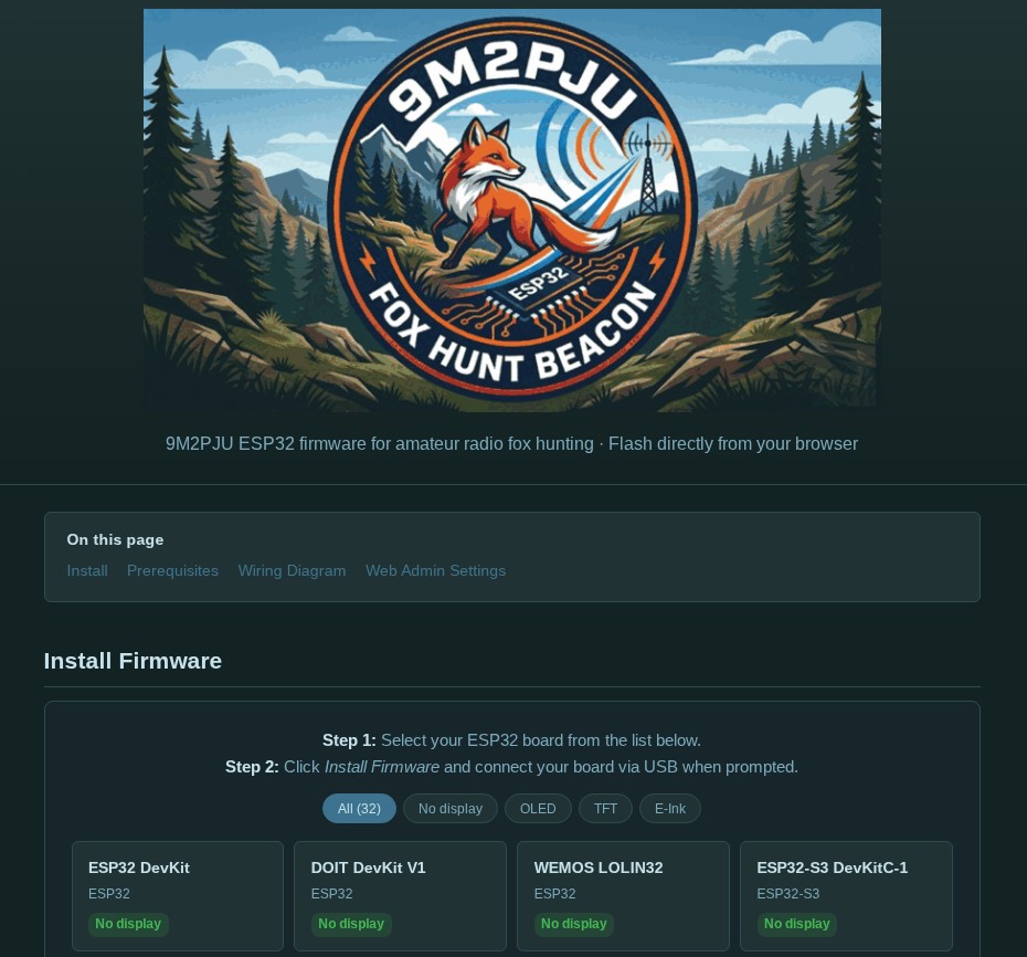
The 9M2PJU ESP32 Fox Hunt Beacon firmware can now be flashed directly from your browser at fox.hamradio.my no software to install, no command line, no PlatformIO setup. Open the page in Google Chrome, Microsoft Edge, or Opera, pick your board from 32 supported ESP32 variants (including generic DevKit boards, Heltec WiFi Kit and LoRa series, LilyGO T-Display, TTGO LoRa32, T-Beam, T-Watch, and more), click Install Firmware, and connect your board via USB. The web flasher uses the Web Serial API to write the correct prebuilt firmware to your ESP32 right through the browser. Once flashed, the beacon boots into WiFi AP mode, connect to the 9M2PJU-Fox-XXXX network on your phone or laptop and browse to http://10.0.0.8/ to configure your callsign, fox ID, IARU timing, CW speed and tone, PTT polarity, battery monitoring, and display settings from a clean web admin UI.
Why This Matters
Fox hunting is one of the oldest living traditions in amateur radio, and it is also one of the most welcoming. You do not need a big shack, a tower, or a fancy radio. You need a handheld, a directional antenna, a pair of walking shoes, and a fox.
By putting the fox side of the equation into open source, on hardware that costs less than a family dinner, and by following the IARU ARDF standard so the beacon plays nicely with real events, the project hopes to lower the barrier for clubs, schools, scout groups, and individual hams who want to run a hunt without buying commercial gear. The more people who build one, test one, and contribute back, the better the firmware gets for everyone.
So build one. Hide one. Hunt one. And if you find a bug, fix it, or at least tell me about it.
73, and may your bearings be true.
Sources and Further Reading
-
- 9M2PJU ESP32 Fox Hunt Beacon web flasher: https://fox.hamradio.my
- HamRadio.my, Amateur Radio Resources, Tools and Reviews: https://hamradio.my/
- About 9M2PJU, Malaysian Amateur Radio Operator: https://hamradio.my/about-9m2pju-malaysian-amateur-radio-operator/
- IARU Region 1 ARDF Working Group: https://www.iaru-r1.org/on-the-air/operating/ardf/


1 comment