amateur radio
history
4:1 balun, amateur radio, antenna experimentation, attic antenna, Carl Mason, crown antenna, Elmira Radio Club, GW0VSW, ham radio, HF antenna, homebrew antenna, Johan Bouwer, LMR400, loop antenna, multiband antenna, NVIS, silent key, small space antenna, VA3JBO, VE3ERC, VE3UTN, wire loop antenna
9M2PJU
1 Comments
The Crown Antenna: A Wire Loop That Hugs the Roof and Works the World
The Crown Antenna: A Wire Loop That Hugs the Roof and Works the World
Not every ham has a 30 meter tower and a five element monobander in the back yard. Most of us make do with a small yard, an attic, a balcony, or a deck. That is exactly the problem the Crown Antenna was built to solve. It is a wire loop antenna shaped like the peaks and valleys of a crown, originally dreamed up in the UK by Carl Mason, GW0VSW, and later expanded and experimented with by members of the Elmira Radio Club (VE3ERC) in Ontario, Canada.
This article is a look at what the Crown Antenna is, where it came from, how the VE3ERC team built and refined one, how it performs, and how you can put up your own version in a surprisingly small footprint.
What Is a Crown Antenna
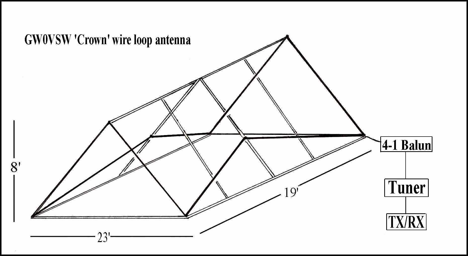
The Crown Antenna is a single, continuous wire loop that is folded up and down into a series of peaks and valleys around its perimeter, so that the outline looks like the jagged top of a royal crown. Instead of a flat horizontal loop sitting at one height, the wire rises to a “peak” at the corners and dips down to a “valley” along the sides. The whole thing is then fed at one point (a corner or the middle of a side) through a balun and coax.
The clever part is the vertical folding. By zig-zagging the wire up and down, you can fit a very long total length of wire into a modest horizontal area. A loop that would normally need a 20 meter by 20 meter flat roof can be squeezed into a much smaller footprint because the wire is “stored” vertically as well as horizontally. That makes the Crown ideal for:
- Attics where you cannot put up anything outside.
- Small backyards where a full size loop would not fit.
- HOA restricted properties where a low profile wire is the only option.
- Field day sites where you want a lot of wire in the air quickly without a tower.
Because it is a closed loop, it also shares the usual loop antenna advantages: it is relatively quiet on receive (loops pick up less local QRM than open ended wires), it presents a mostly balanced load, and with a 4:1 balun it can be tuned across several HF bands with a decent antenna tuner.
Where the Idea Came From
The Crown Antenna was developed by Carl Mason, GW0VSW, who lives in Skewen, near Swansea, in South Wales. Carl’s original version was an indoor attic crown loop built from about 106 feet (32 m) of wire, fitted into the roof space of his house. The “high peaks” of his crown sat at the gable ends of the attic, and the “low peaks” ran along the long side of the house, following the slope of the roof.
Carl has used the indoor Crown loop on the air for years. Beacon logs from as far back as 2008 record him being heard on 10 meters with a QRP Plus transceiver and the indoor Crown loop, and again in 2019 on 10 meters using a Xiegu G90 and the same indoor Crown loop, working stations over 1,200 km away. Not bad for a wire that never leaves the roof.
The idea crossed the Atlantic when Dennis, VE3UTN of the Elmira Radio Club built a small modified version and used it during a field day. Dennis’s version was a small affair, only about 2 feet (0.6 m) high at the peaks and 6 feet (1.8 m) wide, but despite the tiny footprint he used it successfully in digital mode and reportedly racked up close to 80 contacts.
In Memoriam: Carl Mason, GW0VSW (SK 2025)
Carl Mason, GW0VSW, became a silent key in 2025. QRZ now lists his callsign as GW0VSW/SK2025. He was one of the best ham radio friends you could hope to make in Wales, and the kind of operator who would happily answer a stranger’s email and walk them through a problem just because that is what hams do. I exchanged a few emails with Carl over the years, and he once helped me out on a matter when he had absolutely no obligation to. That is the side of amateur radio the rulebooks never quite capture, the willingness to help, just because.
Carl’s background was as interesting as his antenna work. He was a former Royal Navy Submariner in communications and tactical systems, and later a Senior TV Cameraman with BBC Wales. Outside of radio he held a commercial drone licence and a pilot’s licence (PPL/TMG), and he enjoyed radio controlled aircraft and boats, target shooting, and photography. In other words, he was one of those hams whose whole life seemed to revolve around understanding how signals, machines, and the world fit together, whether that was a submarine’s comms suite, a broadcast camera, a drone in the sky, or a folded wire loop in an attic roof.
The Crown Antenna is part of his legacy. This article is, in a small way, a thank you.
The VE3ERC Experiment
Encouraged by Dennis’s field day results, Johan Bouwer, VA3JBO of VE3ERC decided to build a much larger Crown Antenna at his own home and experiment with it properly. What followed is a nice piece of old fashioned ham radio experimentation, documented day by day on the VE3ERC website. It is worth walking through because it shows the kind of iterative tweaking that real antenna work is made of.
Version 1: The 68 by 34 Rectangle
The first expanded Crown at VA3JBO measured 68 feet by 34 feet (20.7 m by 10.3 m). The low points (valleys) were just 2 feet (0.6 m) off the ground, and the high points (peaks) were 12 feet (3.66 m) off the ground. The total wire length was close to 245 feet (74.7 m).
It was corner fed using a 4:1 balun, with 120 feet (36.6 m) of LMR400 coax back to the radio, a Yaesu FT-897D. During a recent contest this version made contacts into Washington state and Georgia, with both stations reporting solid 5 by 9 signal reports. So far, so good.
Friday, September 27: Bringing in the Field Day Radio
Three club members, Al VA3TET, Bruce VA3QB, and Dennis VE3UTN, came over to operate. They brought the club’s tried and true field day transceiver. Several contacts were made, including one as far away as Germany, who came booming in running 500 watts. But after several more hours of operating it became apparent that the antenna’s radiating qualities needed improvement.
Saturday, September 28: Moving the Feed Point
Dennis made a few more contacts, then decided to change the feed point. The antenna had been fed from the north/east corner; he moved the balun to the center of the south/east side. This is one of the beautiful things about a loop, you can move the feed point around the perimeter and the antenna keeps working, just with different impedance and pattern characteristics. The change made some difference, but not enough. Dennis was disappointed with the results (and reportedly asked Johan to take the photos down, though Johan kept them up, because “this is what experimenting is all about”).
Tuesday, October 1: Squaring Up
The next step was to square up the antenna so that there were equal numbers of peaks and valleys on each side, turning the 68 by 34 rectangle into a 68 by 68 foot square. Each angled section of wire now measured 20 feet (6.1 m), and there were 16 sections in total, giving 320 feet (97.5 m) of wire. (Johan noted one side was 2 feet short because of his deck, so the true total was about 318 feet.) The loop was still center fed.
Wednesday, October 2: Back on the Air
The balun was reconnected and the antenna hooked back up to the transceiver. Around 14:00 to 15:00 local time there was not much happening. At 17:30 a station in Sao Paulo was reached, who repeated Johan’s callsign, but conditions worsened and the contact could not be completed. At 19:00 the bands were full of American stations and “could not get a word in edgewise.”
The final configuration was a 68 by 68 foot square Crown, peaks at 12 feet, valleys at 2 feet, covering an area of 4,624 square feet, fed at the center of one side through a 4:1 balun.
What the Experiment Tells Us
A few useful lessons fall out of the VE3ERC Crown story, and they apply to almost any homebrew antenna project.
Loops tolerate a lot of abuse. Throughout the experiment the antenna was reshaped from a rectangle to a square, the feed point was moved from a corner to the middle of a side, and the wire length changed from 245 to 320 feet. It kept loading and making contacts. That resilience is one reason loops are so popular with experimenters.
Feed point position matters. Moving the feed from the corner to the center of the long side changed the impedance and the pattern. On a closed loop, the feed point determines which harmonics are easily excited and where the current maxima sit. There is no single “right” answer, which is why experimenting is worth the effort.
Symmetry helps. Squaring up the antenna so each side had the same number of peaks and valleys was a deliberate attempt to balance the structure. Symmetric loops tend to be easier to tune and produce more predictable patterns.
Low height is not a death sentence. With peaks at only 12 feet and valleys at 2 feet, the Crown is a genuinely low antenna, yet it was making transatlantic and transcontinental contacts on HF. A lot of the “you must be up high” advice applies to gain and DX angle of radiation, but for general working, and especially for NVIS style work on the lower bands, a low loop can be surprisingly effective.
Patience and conditions. Several of the slow periods in the experiment were simply bad band conditions, not bad antenna. The Sao Paulo contact that started but did not complete, and the wall of American stations on 20 meters, are propagation effects, not antenna faults.
Building Your Own Crown Antenna
If you want to try a Crown Antenna yourself, here is a practical recipe based on the GW0VSW and VE3ERC designs.
Materials
- Wire: 14 or 16 AWG stranded copper, insulated. Length depends on your footprint, plan for 250 to 320 feet for a full size HF version.
- Supports: Lightweight fiberglass poles, PVC pipe, or simply the roof structure of an attic. For an outdoor version, short mast sections or even tall garden stakes work for the peaks.
- Balun: A 4:1 current balun is the classic choice for a multiband loop fed with coax.
- Coax: LMR400 or similar low loss coax, especially for long runs.
- Antenna tuner: A wide range tuner at the shack end, because the loop will present very different impedances on different bands.
- Insulators: Egg or dogbone insulators at each peak and valley anchor point.
Layout
- Mark out your perimeter. A square or rectangle works best. The VE3ERC final version was 68 by 68 feet, but you can scale this to whatever space you have.
- Set the peak and valley heights. A typical ratio is peaks at 10 to 12 feet and valleys at 2 to 4 feet. The exact heights are not critical, the point is to fold the wire vertically to fit more length into the footprint.
- Run the wire in a continuous zig-zag around the perimeter, going up to a peak at each corner and down to a valley in the middle of each side. Use 16 sections (4 peaks and 4 valleys per full loop if you want symmetry) of roughly equal length.
- Feed at a corner or the center of a side. Corner feeding with a 4:1 balun tends to favor multiband operation; center of side feeding can give a cleaner pattern on the fundamental band.
- Run coax back to the shack and use a tuner to match on each band.
Tuning
Because the Crown is a closed loop, it will be resonant on multiple harmonics of its fundamental frequency. A 320 foot loop is roughly a full wave on 80 meters (about 270 feet for a flat loop, the extra wire from the folding shifts this around), and it will work on 40, 20, 15, and 10 meters as well, often with a usable SWR after the tuner. Expect the SWR to be all over the place band to band, that is normal for a multiband loop and is exactly what the tuner and balun are there to handle.
Crown Antenna Versus Other Loops
How does the Crown compare to the more familiar loop designs?
Versus a flat horizontal loop. A flat loop at one height is simpler to build and model, but it needs a larger flat area at full height. The Crown trades vertical complexity for horizontal compactness, fitting the same wire into a smaller footprint.
Versus a delta loop. A delta loop is a triangle, usually vertical, fed at a corner or part way up a side. Deltas are great for low angle DX work but need a single tall support. The Crown needs no tall support, just short peaks, which makes it friendlier for attic and HOA restricted installs.
Versus a magnetic loop. A small transmitting magnetic loop is a high Q tuned loop with a capacitor, very compact but limited bandwidth and power handling. The Crown is a full size wire loop, broadband-ish, handles full power, and does not need a tuning capacitor.
Versus a G5RV or fan dipole. Open ended wires like the G5RV are popular and simple, but they are noisier on receive than a closed loop and they need a balanced feed or a good balun to avoid common mode current. The Crown’s closed loop is naturally quieter and more balanced.
Why the Crown Deserves More Attention
The Crown Antenna is not a mainstream design. You will not find it in the ARRL Antenna Book, and most hams have never heard of it. But it sits in a really useful niche: a lot of wire, in a small footprint, low to the ground, multiband, and quiet on receive. For the attic operator, the HOA restricted ham, the field day team that wants a quick deployable loop, or anyone who wants to experiment with a forgiving antenna that can be reshaped on the fly, the Crown is a genuinely interesting option.
It is also a reminder of something the hobby does well: ideas travel. A Welsh ham builds an attic loop, a Canadian club picks up the idea, scales it up, documents the day by day tweaking, and publishes it for the rest of us to learn from. That is amateur radio at its collaborative best.
If you have a small space and a desire to get on the air on HF without a tower, give the Crown a try. The worst that happens is you spend a weekend with a spool of wire and a balun, and learn something about how antennas actually behave. The best that happens is you work the world from a loop that never gets higher than the roof line.
Sources and Further Reading
- VE3ERC Crown Antenna article (Johan Bouwer, VA3JBO): https://www.ve3erc.ca/crown-antenna/
- VE3ERC Antennas page: https://www.ve3erc.ca/antennas/
- VE3ERC About page (club info): https://www.ve3erc.ca/about-ve3erc/
- GW0VSW Carl Mason beacon log (indoor Crown loop, 2008 and 2019): http://www.radiorud.se/log.php?band=10&callsign=GW0VSW
- ARRL Antenna Book (general loop antenna theory): https://www.arrl.org/arrl-antenna-book
- Simple Wire Antennas, a few thoughts and ideas (loop gain vs dipole): https://hamantennas.blogspot.com/2011/02/simple-wire-antennas-few-thoughts-and.html
- Wire Antennas for the Beginner (L. B. Cebik, W4RNL): http://www.antentop.org/w4rnl.001/fdim2.html
- M0MCX Mega Loop (large single element loop performance): https://www.m0mcx.co.uk/xxt-mega-loop-update/








1 comment