CA2RXU LoRa APRS iGate Remote Management: The Definitive Over-the-Air and WebUI Guide
TL;DR: Ricardo Guzman’s (CA2RXU) open-source LoRa APRS iGate and digipeater firmware (V4.0.2) features an over-the-air (OTA) and network-level remote management system designed for inaccessible mast and solar hilltop deployments. By configuring manager callsigns with wildcard support and enabling the RF-only commands toggle, operators can query station health, toggle RF transmission, switch digipeater EcoModes, and commit runtime changes directly via standard APRS text messages without exposure to APRS-IS injection attacks. Combined with authenticated WebUI administration, ElegantOTA firmware uploads, battery voltage sleep guards, and automated reboot watchdogs, it delivers resilient field management for off-grid amateur radio packet networks.
Mounting an amateur radio packet station at the top of a commercial tower, rooftop mast, or remote mountain repeater site is the single most effective way to maximise VHF and UHF radio line-of-sight. For LoRa APRS operating on 433 MHz (such as 433.400 MHz in Malaysia or 433.775 MHz across Europe), height above average terrain is everything. A 100 mW Semtech transceiver connected to a high-gain collinear antenna at 30 metres can easily cover an entire metropolitan basin or mountain valley.
Once an ESP32 LoRa APRS iGate or standalone digipeater is sealed inside an IP67 weatherproof enclosure and hoisted up a pole, physical access becomes a major operational liability. If your receiver suffers local RF desensitisation, if a nearby solar charge controller causes spurious noise, or if consecutive overcast days deplete your battery bank, climbing a tower with a laptop and a USB-to-UART cable in the middle of a monsoon downpour is an awful failure mode.
The open-source LoRa APRS iGate/Digipeater firmware developed by Ricardo Guzman (CA2RXU) provides a broad dual-tier remote management architecture. The firmware gives operators full control over node diagnostics, RF transmitter state, power-saving profiles, and firmware upgrades through two independent pathways: in-band AX.25 APRS messages over radio frequency, and an authenticated WebUI interface over local network links. This guide details exactly how to configure, secure, and operate CA2RXU remote management in real-world field environments.
Last updated: November 2026.
What is CA2RXU LoRa APRS Remote Management?
CA2RXU LoRa APRS remote management is a built-in control architecture within Ricardo Guzman’s ESP32 iGate and digipeater firmware that enables operators to monitor telemetry, toggle RF transmitters, switch power-saving modes, and update firmware over radio frequency (RF) packets or authenticated network interfaces without physical physical access to the device.
Rather than treating an iGate as a passive appliance that requires physical USB reprogramming whenever operating parameters change, the firmware implements two dedicated control planes:
+-----------------------------------------------------------------------------------+
|                        CA2RXU REMOTE MANAGEMENT TOPOLOGY                         |
+-----------------------------------------------------------------------------------+

   +--------------------------+
   |   Mobile LoRa Tracker    |
   |   (e.g., 9M2PJU-7 HT)    |
   +------------+-------------+
                |
                |  In-Band RF APRS Messages
                |  (?APRS?, ?APRSSR, ?TX=OFF, ?EM=ON)
                v
   +--------------------------------------------------------------------------------+
   |  REMOTE CA2RXU NODE (ESP32 + SX1268/SX1278)                                    |
   |                                                                                |
   |  [LoRa RF Front-End] <--- Packet Parsing <--- Whitelist Verification            |
   |         |                                      (Callsign / Wildcard)           |
   |         |                                              |                       |
   |         v                                              v                       |
   |  [Core Firmware Engine] <----------------------- [Security Gate]               |
   |         |                                        (RF-Only Flag Check)          |
   |         +---> Telemetry & Battery Health Guard         |                       |
   |         +---> EcoMode Engine (Normal vs Ultra-Eco)     |                       |
   |         +---> NVS Flash Commit (?COMMIT)               |                       |
   |         |                                              |                       |
   |  [Network Manager]                                     |                       |
   |         |                                              |                       |
   +---------+----------------------------------------------+-----------------------+
             |                                              |
             | Local LAN / WireGuard / SSH Tunnel           | APRS-IS Feed
             v                                              v
   +--------------------------+                   +--------------------+
   |   Browser Admin WebUI    |                   |   APRS-IS Servers  |
   |   • Dashboard & Map      |                   |   (Blocked if      |
   |   • Admin Auth / NVS     |                   |    RF-only is set) |
   |   • ElegantOTA Flashing  |                   +--------------------+
   +--------------------------+
- In-Band RF Control Plane: Designed for remote, solar-powered hilltop digipeaters and standalone iGates without wired network access. Authorised operators issue standard APRS text messages from any handheld LoRa tracker or mobile rig. The firmware parses incoming packets, verifies the sender’s callsign against an internal whitelist, executes operational directives (such as muting the transmitter or entering low-power sleep), and returns an acknowledgement with diagnostic data.
- Out-of-Band Network Management Plane: Designed for internet-connected iGates deployed in shacks, community centres, or remote shelters with Ethernet or Wi-Fi uplinks. This plane provides an interactive Bootstrap-based dashboard, real-time packet inspection tables, live Leaflet map tracking, Syslog output, MQTT telemetry publishing, and web-based firmware updating via ElegantOTA.
Over-the-Air APRS Command Protocol and Query Reference
The heart of CA2RXU’s field management system is its APRS query engine. In standard APRS protocol, queries allow stations to request point-in-time status, capabilities, or diagnostic reports from other stations using addressed text messages.
To issue a command, you address an APRS message directly to the iGate’s station callsign and SSID (for instance, 9M2PJU-10) from an authorised transmitter. When received, the iGate processes the command, applies the requested state change, and transmits a reply message containing the result and an AX.25 message acknowledgement (ack{001}).
+---------------------------------------------------------------------------------------+
| SENDER PACKET:    9M2PJU-7>APL102,WIDE1-1::9M2PJU-10:?APRSSR{01                       |
| NODE PROCESSING:  1. Verify Sender (9M2PJU-7 matches 9M2PJU*) -> ALLOWED              |
|                   2. Extract Payload -> '?APRSSR'                                     |
|                   3. Measure Hardware RF: RSSI=-82dBm, SNR=+9.2dB, FreqErr=+142Hz     |
| NODE REPLY:       9M2PJU-10>APL402,WIDE1-1::9M2PJU-7 :ack01                           |
|                   9M2PJU-10>APL402,WIDE1-1::9M2PJU-7 :RSSI: -82dBm SNR: 9.2dB{02     |
+---------------------------------------------------------------------------------------+
Complete Query Command Reference
The table below outlines every query and management directive supported in CA2RXU firmware V4.0.2:
| APRS Message Query | Target Role | Description | Typical Response / Action |
|---|---|---|---|
?APRS? or HELP |
iGate / Digi | Returns the command index and supported query directives. | Returns summary of valid queries (?APRSV, ?APRSP, ?APRSL, ?APRSSR, etc.). |
?APRSV |
iGate / Digi | Returns the active firmware release version. | CA2RXU LoRa APRS iGate V4.0.2 |
?APRSP |
iGate / Digi | Requests node coordinates (latitude and longitude). | Returns station position truncated to two decimal places for privacy and bandwidth conservation. |
?APRSL |
iGate / Digi | Requests list of stations heard over RF in the last 30 minutes. | Returns comma-separated list of callsigns recorded during the Remember Station Time window. |
?APRSSR |
iGate / Digi | Requests instant Signal Report for the received query packet. | Returns RSSI: -XXdBm SNR: YY.YdB FreqErr: ZZHz of your transmission. |
?EM=? |
Digipeater | Queries the current operational EcoMode state. | Returns EcoMode: OFF or EcoMode: Ultra Eco Mode. |
?EM=ON |
Digipeater | Engages Ultra Eco Mode on the digipeater. | Turns off Wi-Fi AP, OLED/TFT screen, status LEDs, and clocks down CPU frequency. Confirms state change. |
?EM=OFF |
Digipeater | Disengages Ultra Eco Mode, restoring normal mode. | Re-activates Wi-Fi AP and display hardware for local maintenance. Confirms state change. |
?TX=? |
iGate / Digi | Queries whether RF transmission is enabled on the node. | Returns Tx: ENABLED or Tx: DISABLED. |
?TX=ON |
iGate / Digi | Enables LoRa RF transmission. | Activates the RF power amplifier for packet beaconing and digipeating. Confirms Tx: ON. |
?TX=OFF |
iGate / Digi | Shuts down LoRa RF transmission immediately. | Disables transmitter output. Node continues receiving and gating to APRS-IS, but remains RF-silent. |
?COMMIT |
iGate / Digi | Writes volatile runtime states to non-volatile flash (NVS). | Permanently stores active TX and EcoMode settings so they persist across power loss and reboots. |
Diagnostic Queries: Signal Reports and Station Lists
For operators troubleshooting antenna performance or verifying propagation, ?APRSSR is an invaluable tool. Unlike standard voice repeaters where signal assessments are subjective, sending ?APRSSR causes the node to measure the exact physical parameters of your LoRa transmission:
- Received Signal Strength Indicator (RSSI): Measured in dBm. A signal of -60 dBm indicates strong line-of-sight reception, while -118 dBm indicates a signal approaching the thermal noise floor.
- Signal-to-Noise Ratio (SNR): Measured in dB. Semtech SX1268 and SX1278 chips can decode packets buried deep below the noise floor (down to -15 dB at Spreading Factor 10 or -20 dB at Spreading Factor 12).
- Frequency Error / Shift: Measured in Hz. This indicates crystal oscillator drift between your tracker and the remote iGate, allowing you to catch thermal frequency drift before packets drop entirely.
Sending ?APRSL returns the stations currently held in the node’s local memory table. This is critical for diagnosing whether an iGate is hearing regional traffic or suffering from RF receiver deafening caused by a nearby transmitter.
Operational State Control and NVS Persistence
The commands ?TX=OFF and ?TX=ON provide an essential safety disconnect. If your remote digipeater begins repeating bad packets, experiences a software loop, or interferes with adjacent frequency allocations, you don’t need to cut master power. Transmitting ?TX=OFF mutes the RF amplifier while keeping the ESP32 logic, telemetry sensors, and network links alive.
Crucially, changes made via ?TX= or ?EM= are initially stored in volatile RAM. If the node reboots due to a watchdog timer or solar brownout, it will revert to the settings defined in its initial configuration. To make the changes permanent, you must transmit the ?COMMIT command. Upon receiving ?COMMIT, the firmware writes the updated variables directly into ESP32 Non-Volatile Storage (NVS flash memory).
Whitelisting and the Anti-Spoofing Security Architecture
Allowing remote RF control of an unattended radio transmitter presents obvious security risks. If unauthenticated stations could issue ?TX=OFF, malicious actors could trivially disable emergency communication networks. Because amateur radio regulations strictly prohibit encryption on amateur frequencies, standard cryptographic challenge-response handshakes are legally and technically constrained.
CA2RXU firmware implements a robust two-layer security model in the Remote Management menu:
+-----------------------------------------------------------------------------------+
|                        REMOTE MANAGEMENT SECURITY PIPELINE                        |
+-----------------------------------------------------------------------------------+

                          Incoming APRS Message Frame
                                       |
                                       v
                     +-----------------------------------+
                     |  Source Callsign Whitelist Check  |
                     |  (e.g., '9M2PJU-7' vs '9M2PJU*')  |
                     +-----------------+-----------------+
                                       |
                         +-------------+-------------+
                         |                           |
                     No Match                      Match
                         |                           |
                         v                           v
                  [Packet Dropped]       +-----------------------+
                  [No Command Exec]      | Ingress Channel Check |
                                         +-----------+-----------+
                                                     |
                                       +-------------+-------------+
                                       |                           |
                                  APRS-IS Feed                  RF LoRa
                                       |                           |
                        +--------------+-------------+             |
                        | RF-Only Restriction Active?|             |
                        +--------------+-------------+             |
                                       |                           |
                           +-----------+-----------+               |
                           |                       |               |
                          Yes                      No              |
                           |                       |               |
                           v                       v               v
                    [Packet Dropped]       [Process Management Query]
                    [Security Violation]   [Execute Command & Reply]
1. Callsign Whitelisting with Wildcard Support
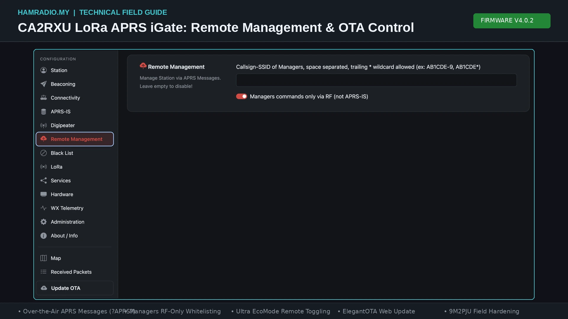
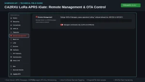
Under the WebUI’s Remote Management tab, the field Callsign-SSID of Managers defines exactly which stations hold administrative privileges.
- Specific Callsign Binding: Entering
9M2PJU-7 9M2PJU-9grants access exclusively to packets transmitted with those precise SSIDs. A packet from9M2PJU(SSID 0) or9M2PJU-10will be rejected. - Wildcard Matching: The firmware supports a trailing asterisk (
*) wildcard. Configuring9M2PJU*authorises every SSID originating from the base callsign9M2PJU(from9M2PJU-0through9M2PJU-15). Multiple manager callsigns are separated by spaces:
9M2PJU* 9W2xxx-7 9M4xxx*
If the Callsign-SSID of Managers field is left blank, the entire remote management query processor is disabled. The node will ignore all incoming control messages.
2. The RF-Only Restriction (Preventing APRS-IS Injection)
The single most critical security setting in the firmware is the toggle labeled:
[x] Managers commands only via RF (not APRS-IS)
Understanding why this setting is vital requires looking at how the global APRS-IS network works. APRS-IS authentication relies on a rudimentary algorithm known as the APRS passcode. This passcode is a simple mathematical hash of the callsign, designed in the 1990s purely to prevent accidental misconfigurations rather than to withstand determined attackers. Passcode calculators are widely available online.
If an iGate connects to APRS-IS and the RF-only restriction is disabled, anyone anywhere in the world connected to an APRS-IS server can craft a raw APRS packet with your callsign (e.g. 9M2PJU-7>APRS::YOURNODE:?TX=OFF), upload it to the internet feed, and your iGate will pull that packet from APRS-IS and execute it.
When you enable Managers commands only via RF, the firmware enforces an strict hardware boundary:
- Incoming packets arriving over the Wi-Fi/Ethernet APRS-IS TCP socket are flagged as internet-originated.
- Even if the callsign on the APRS-IS packet matches your manager whitelist, the security gate drops the packet instantly.
- Only packets received directly through the onboard Semtech LoRa radio chip with valid RF physical preamble, CRC, and header data are processed.
For any internet-connected iGate, enabling this option is non-negotiable.
Network Administration and WebUI Hardening
While RF commands handle field operations, the built-in HTTP WebUI provides broad configuration management for connected iGates. Accessible via any standard web browser, the WebUI is divided into sixteen specialised management panels.
+-----------------------------------------------------------------------------------+
|                         CA2RXU V4.0.2 WEBUI SIDEBAR LAYOUT                        |
+-----------------------------------------------------------------------------------+
|  [CONFIGURATION]         |  [MONITORING & TOOLS]      |  [ADMIN & MAINTENANCE]     |
|  • Station Setup         |  • Map (Leaflet Live)      |  • Administration (Auth)   |
|  • Beaconing Profile     |  • Received Packets (SNR)  |  • ElegantOTA Firmware     |
|  • Connectivity (Wi-Fi)  |  • About / System Info     |  • JSON Backup & Restore   |
|  • APRS-IS Feed          |                            |  • Forced Reboot Control   |
|  • Digipeater Modes      |                            |                            |
|  • Remote Management     |                            |                            |
|  • Black List Filtering  |                            |                            |
|  • LoRa Radio Tuning     |                            |                            |
|  • Services (TNC/Syslog) |                            |                            |
|  • Hardware & Battery    |                            |                            |
|  • WX Telemetry I2C      |                            |                            |
+-----------------------------------------------------------------------------------+
WebUI Authentication Credentials
By default, the WebUI doesn’t enforce password protection. When deploying on a home local area network or a shared club repeater subnet, authentication must be activated immediately under Administration:
- Admin Web Interface Authentication: Set a strong administrative username and password. Once saved and rebooted, accessing the configuration interface requires standard HTTP basic authentication.
- OTA Update Authentication: The firmware provides a secondary, independent credential layer specifically for firmware flashing. Setting a unique OTA username and password ensures that even if someone gains view access to your local subnet, they can’t overwrite the ESP32 flash partition.
Note: Use alphanumeric characters only for both usernames and passwords to avoid string truncation or encoding corruption inside ESP32 SPIFFS configuration storage.
Secure Remote Networking: Tunnels vs Port Forwarding
An all-too-common mistake in amateur radio is forwarding external port 80 on a home router directly to an ESP32 board. Embedded microcontrollers running lightweight HTTP daemons (such as ESPAsyncWebServer) aren’t designed to withstand automated internet botnets, Slowloris denial-of-service floods, or memory corruption exploits.
Never expose your iGate’s WebUI directly to the public internet. Instead, implement one of three robust remote access strategies:
- Local SSH Port Forwarding Tunnel: If your iGate shares a local network with a lightweight Linux server (such as a Raspberry Pi or DietPi node), forward the WebUI port securely across an encrypted SSH connection:
bash

# Establish an encrypted SSH tunnel forwarding local port 8080 to the remote iGate IP

ssh -o ServerAliveInterval=30 -o ServerAliveCountMax=3 -N -L 8080:10.0.1.112:80 [email protected]
Openinghttp://localhost:8080in your local browser grants full, secure access to the node without exposing port 80 to the WAN. - Overlay Mesh VPNs (Tailscale / WireGuard): Install a VPN client on a small gateway device on the node’s local network. Tailscale provides smooth traversal across carrier-grade NAT (CGNAT) connections commonly found on 4G and 5G cellular broadband routers.
- Hardened Reverse Proxy: If direct domain access is strictly required, place the node behind Nginx or Caddy configured with TLS certificates, IP rate limiting, and HTTP basic authentication.
Connectivity Failover and the Wi-Fi Auto-AP Watchdog
Remote sites frequently suffer from intermittent Wi-Fi coverage or broadband dropouts. CA2RXU firmware incorporates several automated fallback mechanisms under Connectivity:
- Multi-SSID Stacking: Operators can store multiple Wi-Fi credentials. If the primary site access point drops, the node cycles through the secondary entries until an active connection is established.
- Startup Delay: Configurable up to 5 minutes (default: 0). At remote sites where power is restored simultaneously after a blackout, consumer routers often take 2-3 minutes to boot their Wi-Fi radios. Setting a 2-minute startup delay prevents the ESP32 from exhausting its connection attempts before the router is ready.
- Wi-Fi Auto-AP Mode: If all configured Wi-Fi connections fail, the node automatically spins up its own standalone access point named
NOCALL-10(or based on the configured callsign) with a default password of1234567890. - Auto-AP Timeout: Defines how many minutes the rescue access point remains active (default: 10 minutes) before the board shuts down the AP and rescans for upstream Wi-Fi networks. This prevents a temporary network outage from locking the iGate into an isolated AP state indefinitely.
Remote Hardware Health Monitoring and Telemetry
Unattended installations require continuous insight into electrical power, thermal conditions, and battery reserve margins. The firmware provides native support for analogue voltage monitoring, digital I2C bus sensors, and automated low-voltage sleep routines.
Analogue vs I2C Battery Telemetry
Monitoring battery supply voltage is supported through two distinct methods configured under Hardware > Battery:
Method 1: Direct ESP32 Analogue-to-Digital Converter (ADC)
+----------------+      R1 (100k)      +-------------+      R2 (27k)      +--------+
| Battery (+)    |-----[/\/\/\/\/\\]---+---| ADC Pin |---[/\/\/\/\/\\]----+ Ground |
| (Up to 15.0V)  |                     |   | (GPIO)  |                    |        |
+----------------+                     +-------------+                    +--------+
                                       (Division Ratio: ~4.7:1)

Method 2: External I2C Sensor (INA219 High-Side Monitor)
+----------------+                     +-------------+                    +--------+
| Battery (+)    |---------------------+--[ INA219 ]-+--------------------+ System   |
+----------------+                     |  (I2C Bus)  |                    +--------+
                                       +------+------+
                                              | SDA/SCL
                                              v
                                       +-------------+
                                       | ESP32 GPIO  |
                                       +-------------+
- Built-in ADC Voltage Divider: For simple installations, the ESP32 ADC reads voltage via a two-resistor voltage divider (standard: 100k ohm R1 and 27k ohm R2, supporting inputs up to 15 V). You can calibrate the exact resistor ratio inside the WebUI to compensate for standard resistor tolerances.
- Digital I2C INA219 Sensor: For precision telemetry, enabling
Use External I2C Voltage Sensordirects the firmware to poll an INA219 sensor over the I2C bus. The INA219 measures bus voltage, current draw, and power dissipation directly on a calibrated digital shunt, completely bypassing the non-linear ADC issues native to older ESP32 silicon.
Low-Voltage Sleep Protection (Battery Health Guard)
Deep discharging a lithium-ion (Li-ion) or lithium iron phosphate (LiFePO4) battery pack past its critical threshold destroys battery capacity and can trigger catastrophic cell failure. CA2RXU firmware includes an automated low-voltage watchdog:
- Monitor Internal / External Voltage Health: When enabled, the MCU compares the measured supply voltage against a user-defined sleep threshold (e.g., 3.3 V for an internal 18650 cell, or 11.8 V for an external 12 V LiFePO4 pack).
- Automated Deep Sleep: If the voltage falls below the safety floor, the ESP32 enters deep sleep for 30 minutes, cutting power consumption to microamps. After 30 minutes, the chip wakes briefly, reads the supply voltage to check if solar charging has begun, and either resumes full operation or immediately returns to deep sleep.
Warning: Never enable voltage monitoring without a battery or valid voltage source connected to the designated pin. If left floating, the ADC reads zero volts and the firmware will immediately enter an endless deep sleep loop.
Environmental Telemetry and Base91 Encoding
Connecting an environmental sensor to the I2C bus allows the station to act as a remote weather station. Under WX Telemetry, the firmware scans the I2C bus on boot and auto-detects:
- Bosch Sensortec BME280 / BME680: Temperature, relative humidity, and barometric pressure (plus gas resistance on the BME680).
- BMP280: Barometric pressure and temperature.
- Silicon Labs Si7021: High-accuracy relative humidity and temperature.
The firmware handles pressure altitude correction automatically via the Height Correction setting. Weather data can be broadcast as a dedicated APRS weather report or interleaved into the standard station position beacon as Base91-encoded telemetry to conserve RF channel capacity.
Over-the-Air Firmware Upgrades with ElegantOTA
Upgrading the firmware on a physical board mounted high on an antenna mast used to mean dismounting the entire enclosure. CA2RXU integrates the open-source ElegantOTA web flasher into the firmware build, enabling zero-touch over-the-air binary updates over the network.
+-----------------------------------------------------------------------------------+
|                        ELEGANTOTA REMOTE FLASHING WORKFLOW                        |
+-----------------------------------------------------------------------------------+

   1. Download Release
      Official GitHub Repo ---> Download Board Package (e.g., TTGO_T3S3_V1_2.zip)
                                                  |
   2. Extract Binary File                         v
      Archive File ---------------------> [ota_update.bin]
                                                  |
   3. Access Remote Web Interface                 v
      Browser / Tunnel ---------------> http://<node-ip>/update
                                                  |
   4. Authenticate & Upload                       v
      Enter OTA Credentials ----------> Select 'ota_update.bin' ---> [Upload]
                                                  |
   5. ESP32 Flashing Execution                    v
      Dual-Partition Switch ----------> Flash Written to Inactive OTA Partition
                                                  |
   6. Automated Reboot                            v
      Watchdog Verification ----------> Boot into Updated Firmware
                                        (Configuration Preserved in NVS)
Step-by-Step OTA Upgrade Procedure
- Download Board Firmware: Navigate to the official CA2RXU LoRa APRS iGate GitHub Releases page. Download the
.ziparchive matching your exact hardware board, RF frequency, and display type. - Extract the Binary: Decompress the archive and locate the compiled binary file:
ota_update.bin. - Open the Update Interface: Navigate to
http://<your-node-ip>/updatein your browser (or via your local SSH tunnel). - Authenticate: If OTA authentication is enabled, enter the credentials configured in the Administration panel.
- Upload the Firmware: In the ElegantOTA web interface, ensure the mode is set to Firmware, click Select File, select
ota_update.bin, and click the upload button. - Watch the Transfer: The browser streams the binary into the ESP32’s secondary OTA flash partition. A progress bar will track the upload.
- Reboot and Verification: Once the transfer reaches 100%, the ESP32 verifies the MD5 checksum, marks the new partition as active, and reboots automatically. All configuration parameters stored in NVS remain completely intact.
Comparative Analysis: Remote Management Architectures
How does CA2RXU’s remote management system compare to traditional packet TNCs, modern software-defined setups, and mesh communication frameworks?
| Feature / Metric | CA2RXU LoRa APRS (V4.0.2) | Classic AX.25 TNC (Kantronics / PK-232) | Dire Wolf on Raspberry Pi | Meshtastic Firmware |
|---|---|---|---|---|
| In-Band RF Commands | Yes (APRS text queries with ACK handshake) | Yes (Terminal command mode via remote sysop) | No (Requires external scripts or third-party APRS clients) | Yes (Admin channel protobuf packets) |
| RF Anti-Spoofing | Callsign whitelist with strict RF-only ingress check | Sysop password / challenge password | Host-level OS security | Cryptographic Ed25519 public/private keys |
| Network Interface | Embedded Bootstrap WebUI + Leaflet map | None (RS-232 serial only) | None natively (Requires third-party Web dashboards) | WebUI over Wi-Fi / Bluetooth BLE app |
| Over-the-Air Upgrades | ElegantOTA via web browser | No (EPROM chip replacement required) | Linux OS package manager (apt upgrade) |
Web flasher / Bluetooth OTA |
| Idle Power Consumption | ~7 to 13 mA (Ultra Eco Mode) | 30 to 100 mA (Plus radio receiver draw) | 350 to 600 mA (High power requirement) | ~10 to 25 mA (Deep sleep mesh routing) |
| Battery Health Protection | Native sleep thresholds with auto deep-sleep recovery | External battery protection circuit required | External hardware UPS / shutdown daemon | Built-in battery ADC telemetry |
| Telemetry Integration | I2C (BME280/INA219) + Base91 encoding | Analogue telemetry inputs on select models | Python scripts interfacing with Linux I2C | Direct I2C sensor telemetry |
| Hardware Platform | Low-cost ESP32 / SX126x / SX127x boards | Legacy 8-bit / 16-bit dedicated microprocessors | Single-board computer (SBC) + USB Audio Interface | ESP32, nRF52840, RP2040 |
Practical Field Deployment Checklist
Before sealing your iGate or digipeater inside its weather-sealed enclosure and hoisting it up a mast, execute this pre-flight hardening checklist:
[ ] 1. RF Managers Whitelist Configured
       Enter all authorised operator callsigns (with trailing wildcards if needed)
       in the 'Callsign-SSID of Managers' field.

[ ] 2. RF-Only Commands Toggle Activated
       Confirm that 'Managers commands only via RF (not APRS-IS)' is checked.
       This prevents internet-based APRS-IS command injection.

[ ] 3. WebUI and OTA Credentials Set
       Change default credentials under Administration. Configure distinct passwords
       for both WebUI access and ElegantOTA firmware uploads.

[ ] 4. Multi-SSID and Auto-AP Configured
       Enter primary and backup Wi-Fi credentials. Configure a 2-minute startup delay
       to account for slow-booting site routers. Verify Auto-AP timeout is set to 10 minutes.

[ ] 5. Automated Hardware Reboot Scheduled
       Enable 'Reboot Mode Active' and set the timer between 12 and 24 hours.
       This flushes ESP32 heap memory and resets radio SPI interfaces automatically.

[ ] 6. Battery Sleep Thresholds Calibrated
       If running on solar power, measure the voltage divider ratio with a multimeter.
       Set the 'Sleep Voltage' cutoff above the battery's critical discharge threshold.

[ ] 7. Configuration Backup Saved
       Click 'Download Configuration' to export a full .json backup of your settings
       to your local workstation.

[ ] 8. End-to-End Field Verification
       From a mobile tracker, send an addressed message containing '?APRSSR' to your node.
       Verify that the node returns an accurate signal report and AX.25 ACK.
The Value of Resilient Node Management
Building an amateur radio network that can withstand extreme weather, power grid failures, and remote isolation requires more than just good RF propagation. It requires a management layer that respects physical reality. Climbing a communications tower or traveling miles into the backcountry to fix an unresponsive node is a preventable logistical burden.
Ricardo Guzman’s (CA2RXU) firmware balances accessible, modern web interfaces with in-band, off-grid radio frequency control. By taking the time to configure manager whitelists, lock down RF-only restrictions, and establish secure network tunnels, you transform a modest ESP32 microcontroller and LoRa transceiver into a resilient, maintainable communications asset that serves your local amateur radio community reliably for years to come.
Sources and Further Reading
- CA2RXU LoRa APRS iGate Repository: https://github.com/richonguzman/LoRa_APRS_iGate
- LoRa APRS iGate / Digipeater Firmware Manual V4.0.2: Ricardo Guzman (CA2RXU), Valparaíso, Chile (October 2026).
- CA2RXU Web Flasher Utility: https://richonguzman.github.io/lora-igate-web-flasher/installer.html
- APRS Working Group Specification (APRS 1.01): http://www.aprs.org/doc/aprs101.pdf
- APRS 1.2 Addendum Specifications: http://www.aprs.org/aprs12.html
- RadioLib Universal Wireless Communication Library: https://github.com/jgromes/RadioLib
- ElegantOTA Library Documentation: https://docs.elegantota.pro/
- 9M2PJU Mod LoRa APRS Tracker Guide: https://hamradio.my/9m2pju-mod-lora-aprs-tracker-malaysia/
- LoRa APRS iGate V4.0.0 Architecture & Map Overview: https://hamradio.my/lora-aprs-igate-v4-webui-cad-stations-map/
- APRS-IS Passcode & Protocol Reference: http://www.aprs-is.net/
73 de 9M2PJU.


Post Comment