ESP-SDR: Turn ESP32 Microcontrollers into Raw I/Q Software-Defined Radios
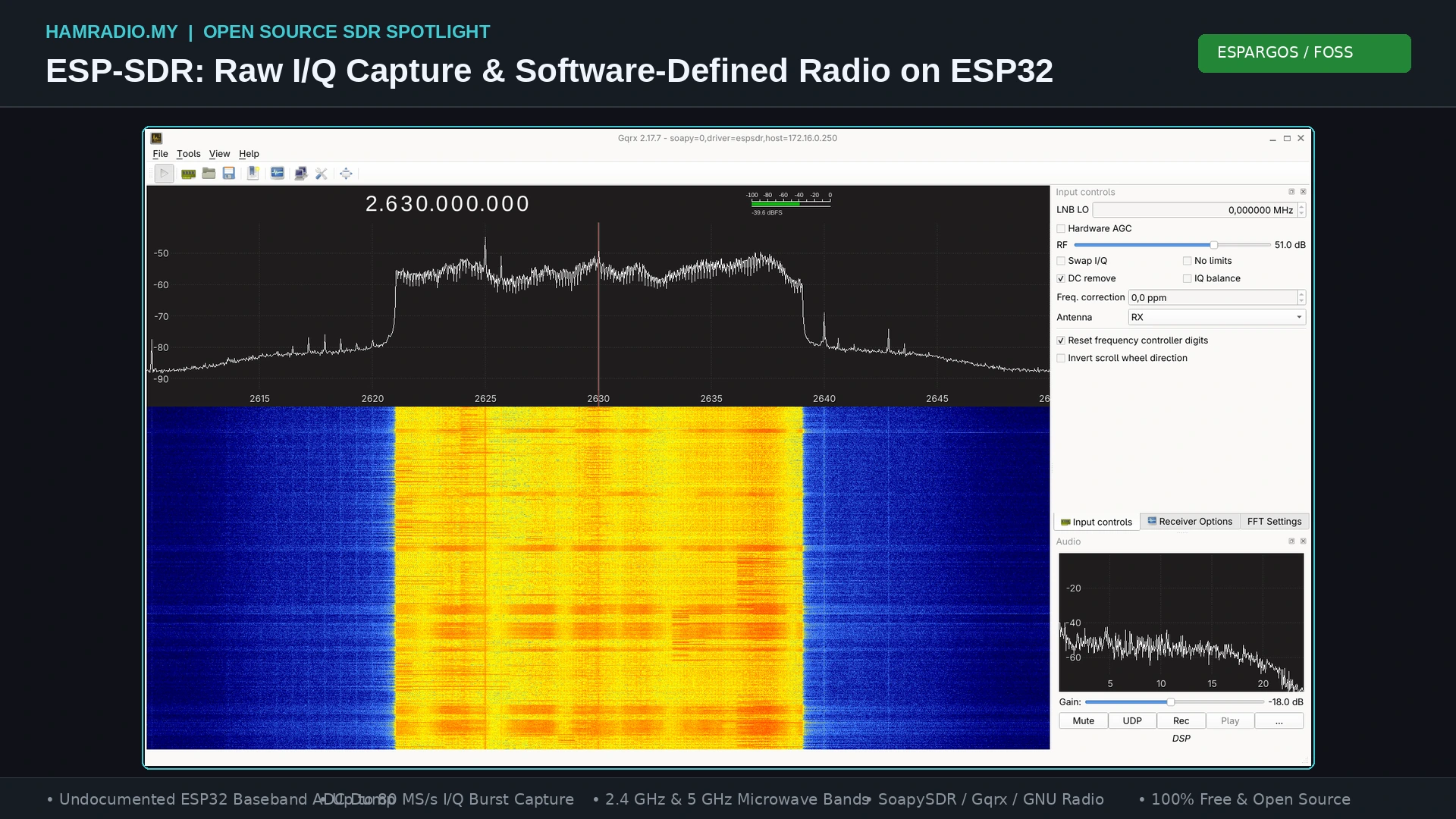
TL;DR: ESP-SDR is an open source firmware and driver ecosystem created by ESPARGOS that turns standard ESP32 microcontrollers into receive-only software-defined radios. By repurposing an undocumented internal baseband dump engine originally used during factory RF testing, ESP-SDR captures raw I/Q samples directly from the on-chip receiver at up to 80 MS/s without needing extra hardware. It supports spectrum analysis, dual-core decimated I/Q streaming on ESP32-S3, high-speed 40 MS/s streaming on ESP32-S31 via Ethernet, and smooth integration with Gqrx, SDR++, and SoapySDR.
What Is ESP-SDR?
ESP-SDR is an open source firmware and driver project developed by ESPARGOS that transforms standard Espressif ESP32 microcontrollers into receive-only software-defined radios capable of raw I/Q baseband capture up to 80 MS/s without auxiliary SDR hardware.
For years, software-defined radio enthusiasts and amateur radio operators have relied on dedicated hardware dongles like the RTL-SDR, HackRF, or Airspy to explore the radio frequency spectrum. While these dedicated receivers deliver excellent sensitivity and broad frequency agility, they require specialized RF tuner silicon, discrete analog-to-digital converters, and high-speed USB interface chips. Meanwhile, hundreds of millions of ESP32 microcontrollers sit on workbenches, IoT devices, and development boards worldwide, each containing a capable 2.4 GHz (and in newer models, 5 GHz) RF transceiver with integrated low-noise amplifiers, mixers, variable-gain amplifiers, and fast ADCs.
Under normal operation, Espressif’s proprietary PHY and baseband firmware tightly couples the receiver ADC output directly to a fixed-function hardware modem designed strictly for 802.11 Wi-Fi, Bluetooth Classic, or Bluetooth Low Energy (BLE) demodulation. The central processing unit (CPU) never sees the raw, unadulterated high-speed radio samples; it only receives high-level MAC-layer frames.
ESP-SDR breaks this fundamental limitation. By identifying and controlling an undocumented silicon debug path embedded deep inside the ESP32 radio subsystem, the ESPARGOS team rerouted raw digitized baseband I/Q samples away from the Wi-Fi modem and directly into on-chip SRAM. The result is a fully functional, zero-cost SDR receiver that turns ubiquitous 3-dollar IoT boards into microwave spectrum analyzers, packet sniffers, and baseband data loggers.
       [ ESP-SDR Baseband Bypass Architecture ]

Antenna ──> LNA/Mixer ──> Filter ──> ADC ──┬──> Wi-Fi / BT Modem (Normal Path)
                                           │
                                           └──> "Dump" Engine (Undocumented)
                                                     │
                                                     ▼
                                                 SRAM Bank
                                                     │
                                                     ▼
                                              ESP32 Dual-Core
                                                     │
                                                     ▼
                                            USB / UART / Ethernet
How the Capture Engine Works
The capture mechanism underpinning ESP-SDR was discovered by reverse-engineering Espressif’s closed-source RF calibration and test library (librftest.a), specifically around a factory diagnostic routine named adctrig.
Espressif engineers included internal hardware hooks on the silicon die to evaluate receiver linearity, noise figures, and gain tables during manufacturing and post-silicon validation. This hardware block, referred to by the developers as the dump engine, connects between the output of the baseband ADC and the internal bus matrix. When activated, it hijacks memory bus cycles and streams 32-bit sample words directly into specific banks of on-chip Static RAM (SRAM) at sample rates of 16, 40, or 80 MS/s.
Executing a stable capture without crashing FreeRTOS or corrupting firmware execution requires careful low-level memory arbitration:
1. Guarding Memory Regions from Heap Allocations
The dump engine doesn’t write through the CPU’s memory management cache. It directly targets fixed physical SRAM blocks. For example, on the ESP32-C3, the dump engine streams data directly into the SRAM block located at 0x3fcb0000. If FreeRTOS were to allocate a task stack, dynamic buffer, or network packet into this address range, the incoming RF sample dump would catastrophically overwrite memory structures.
ESP-SDR isolates this memory space using both ESP-IDF memory reservation macros and custom linker scripts:
SOC_RESERVE_MEMORY_REGION(0x3fca0000, 0x3fcc0000, c3_rf_dump);
The linker script (sram_guard.ld) guarantees that the compiler never places static program variables, data segments, or BSS sections into the capture window.
2. Canaries and Buffer Priming
Before triggering the RF hardware, the CPU fills the target SRAM buffer with a known 32-bit canary sentinel value (0xa5a0055a). When the capture completes, the firmware inspects the buffer boundaries. Any memory word still bearing the canary value indicates an incomplete or truncated capture, allowing the firmware to cleanly report an error rather than passing stale or invalid memory data to the host.
3. Transferring SRAM Ownership
SRAM blocks on Espressif silicon feature bus arbitration registers that govern write permissions. On the ESP32-C3, the SRAM_OWNER_REG at address 0x600c1020 determines whether the CPU or the RF dump engine owns the bus:
REG_WRITE(SRAM_OWNER_REG, (owner & ~7u) | 2u | 8u);
Setting these register bits grants exclusive write access to the dump engine. While the dump engine holds ownership, the CPU can’t read the designated SRAM block; attempts to do so return bus error patterns (such as a repeating four-word pattern on the C3). Consequently, the capture sequence is executed inside an atomic FreeRTOS critical section with interrupts disabled.
4. Debug Lane Multiplexing
The radio baseband contains an internal diagnostic multiplexer that exposes various signals across internal measurement lanes. On the ESP32-C3, the lane selection register 0x60033d90 contains four 6-bit fields:
REG_WRITE(0x60033d90, (0 << 0) | (1 << 6) | (2 << 12) | (3 << 18));
Selecting lanes 0, 1, 2, and 3 routes the raw in-phase (I) and quadrature-phase (Q) outputs from the receiver ADC directly into the 32-bit word stream, cleanly bypassing all downstream Wi-Fi equalization, channel estimation, and digital filtering blocks.
5. Triggering the Capture
The capture is initiated via a central dump control register (0x60033d5c on the ESP32-C3). Setting the enable bit commands the hardware to record a predetermined burst of samples. At an 80 MS/s sample rate, a maximum snapshot buffer of 16,380 samples fills in approximately 205 microseconds. The CPU polls the completion flag, restores SRAM ownership back to the system bus, clears the control registers, and exits the critical section.
Sample Structure and Word Framing
Every sample captured by the ESP32 dump engine is organized as a single 32-bit little-endian integer word:
 31        28 27                20 19                10 9                 0
┌────────────┬────────────────────┬────────────────────┬────────────────────┐
│  (unused)  │  Gain Index (8-bit)│  Q (10-bit signed) │  I (10-bit signed) │
└────────────┴────────────────────┴────────────────────┴────────────────────┘
The word layout reveals key technical characteristics of Espressif’s receiver silicon:
- I (In-Phase) Component (Bits 0-9): A 10-bit signed two’s complement integer representing the real component of the baseband signal.
- Q (Quadrature) Component (Bits 10-19): A 10-bit signed two’s complement integer representing the imaginary component of the baseband signal.
- Receiver Gain Index (Bits 20-27): An 8-bit value recording the hardware gain stage active when the sample was digitized. This provides host applications with an accurate log of automated gain control (AGC) activity during signal bursts.
- Unused Header (Bits 28-31): Reserved bits reserved for internal status flags.
The firmware supports multiple capture formats over the wire:
– CAP: Streams the raw, uncompressed 32-bit words over the serial interface.
– CAP20: Bit-packs the full 10-bit I and 10-bit Q components (20 bits total) to maximize throughput over serial links.
– CAP16: Truncates each component to its most significant 8 bits (signed int8), creating an interleaved 16-bit complex pair ideal for rapid waterfall rendering.
Because these digitized I/Q values originate directly at the output of the receiver ADC prior to any digital decimation or protocol filtering, ESP-SDR detects any RF energy present within the receiver’s instantaneous passband, whether it is standard Wi-Fi, Bluetooth, Zigbee, microwave radar, or an amateur radio digital transmission.
Supported ESP32 Chips and Hardware Capabilities
The ESP-SDR project spans the broad ecosystem of Espressif silicon, unlocking software-defined reception across multiple architecture generations:
| Chip Model | Architecture | Native USB | Max Sample Rate | Continuous Capture | Tuning Range | Key Capabilities |
|---|---|---|---|---|---|---|
| ESP32 (Original) | Xtensa Dual-Core | No (UART0) | 80 MS/s | No (Burst only) | 1.85 – 2.6 GHz | First generation; requires reliable 2 Mbaud UART bridge. |
| ESP32-C2 | RISC-V Single-Core | No (UART0) | 80 MS/s | No (Burst only) | 1.85 – 2.6 GHz | Compact 32 KiB buffer; 26 MHz crystal requires custom build. |
| ESP32-C3 | RISC-V Single-Core | USB Serial/JTAG | 80 MS/s | No (Burst only) | 1.85 – 2.6 GHz | Ubiquitous and inexpensive; simple memory architecture. |
| ESP32-C5 | RISC-V Dual-Band | USB Serial/JTAG | 80 MS/s | No (Burst only) | 2.4 GHz & 5 GHz | Dual-band reception; covers 5 GHz ISM and U-NII bands. |
| ESP32-C6 | RISC-V Single-Core | USB Serial/JTAG | 80 MS/s | Yes (256 FFT bins) | 1.95 – 2.6 GHz | Wi-Fi 6 / 802.15.4; supports continuous ring spectrum mode. |
| ESP32-C61 | RISC-V Single-Core | USB Serial/JTAG | 80 MS/s | Yes (256 FFT bins) | 1.95 – 2.6 GHz | Target chip for ESPARGOS One antenna array; optimized PHY. |
| ESP32-H2 | RISC-V Single-Core | USB Serial/JTAG | 32 MS/s | No (Burst only) | 2.4 GHz (BLE/Zigbee) | Narrower baseband filter (4-11 MHz); firmware AGC mode. |
| ESP32-S2 | Xtensa Single-Core | USB-OTG CDC | 80 MS/s | No (Burst only) | 1.85 – 2.6 GHz | 48 KiB capture memory; native USB CDC console. |
| ESP32-S3 | Xtensa Dual-Core | USB Serial/JTAG | 80 MS/s | Yes (All FFT sizes) | 1.85 – 2.6 GHz | Continuous decimated I/Q streaming over native USB. |
| ESP32-S31 | Xtensa Dual-Core | USB High-Speed | 80 MS/s | Yes (Streaming) | 1.85 – 2.6 GHz | Up to 40 MS/s streaming via PARLIO DMA and Gigabit Ethernet. |
ESP-SDR vs Traditional SDR Hardware
To understand where ESP-SDR fits into an RF enthusiast or radio amateur’s toolkit, consider how it compares to popular dedicated SDR platforms:
| Feature | ESP-SDR (ESP32-S3 / C5) | RTL-SDR v4 | HackRF One | Airspy HF+ Discovery |
|---|---|---|---|---|
| Typical Cost | $3 – $10 | $35 – $45 | $300 – $350 | $170 |
| RF Tuning Range | 1.85 – 2.6 GHz (C5: 5 GHz) | 500 kHz – 1.76 GHz | 1 MHz – 6 GHz | 0.5 kHz – 31 MHz, 60 – 260 MHz |
| Native Bandwidth | Up to 80 MHz burst; 250 kHz stream | 2.4 MHz continuous | 20 MHz continuous | Up to 768 kHz continuous |
| ADC Resolution | 10-bit raw (effective ~7-8 ENOB) | 8-bit | 8-bit | 18-bit DDC architecture |
| Host Connectivity | Native USB-C / UART / Ethernet | USB 2.0 High Speed | USB 2.0 High Speed | USB 2.0 High Speed |
| Standalone Operation | Yes (on-chip FFT, web server, Wi-Fi) | No (Host PC required) | No (Host PC required) | No (Host PC required) |
| Form Factor | Microcontroller dev board | USB Dongle | Metal Enclosure | Metal Enclosure |
| Primary Use Case | Microwave band monitoring, IoT RF | HF/VHF/UHF general receiver | Wideband lab exploration | High-dynamic-range HF/VHF DX |
While dedicated dongles like the RTL-SDR offer broad continuous sub-GHz tuning, ESP-SDR provides access to the 2.4 GHz and 5 GHz microwave bands where RTL-SDR tuners can’t operate without expensive downconverters.
Capture Modes: From Fast Bursts to Continuous Streams
ESP-SDR implements four distinct operational modes tailored to different hardware architectures and throughput requirements:
1. Burst Snapshot Capture (All Supported Chips)
The baseline operational mode captures a single discrete burst of baseband data (up to 16,380 samples) directly into SRAM at 80, 40, or 16 MS/s. Once the dump completes, the CPU packages the buffer into CRC32-checksummed binary frames and transmits them across the serial port.
Because the receiver pauses while the CPU drains the buffer, snapshot captures contain temporal gaps between consecutive bursts. This mode is lightweight, operates reliably even over standard 2 Mbaud UART adapters, and powers the instant waterfall displays in the project’s browser-based viewer.
2. On-Chip FFT Spectrum Mode
Rather than transmitting high-bandwidth raw sample streams to a host PC, the ESP32 CPU can compute Fast Fourier Transforms directly on-chip. Using optimized assembly kernels from Espressif’s esp-dsp library (including SIMD-accelerated radix-2/4 kernels on the ESP32-S3), the microcontroller computes 256, 512, 1024, or 2048-bin complex FFTs in real time.
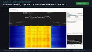
In the case of the ESP32-C6, C61, S3, and S31 over native USB, the firmware employs continuous dual-buffered capture: while the CPU calculates the FFT and sends power spectral density bins across USB, the dump engine fills the alternate SRAM bank. The browser viewer indicates the percentage of the signal captured without interruption as “FFT Coverage.” The high-speed S3 Turbo Mode, originally architected by Zoltan Doczi from Z2Labs, enables smooth real-time RF sweeps across wide 2.4 GHz channels.
3. Continuous Decimated I/Q Streaming (ESP32-S3)
For applications requiring an uninterrupted, gapless baseband feed into software-defined radio suites like SDR++, SDR#, or Gqrx, the ESP32-S3 uses its dual-core Xtensa architecture:
- Core 0: Manages the USB Serial/JTAG communications stack, FreeRTOS housekeeping, and command processing.
- Core 1: Functions as a dedicated digital signal processor (DSP).
The DSP worker drains a continuous 16 MS/s raw ring buffer and applies a two-stage decimation pipeline:
- Stage 1 (Decimate by 8): Unpacks raw ring words into separate 16-bit I and Q arrays scaled by 64 using the
ee.vunzip.16vector instruction. It executes a 32-tap filter combining a squared 8-sample boxcar with an 18-tap Kaiser low-pass filter. This design places double transmission zeros precisely at multiples of $f_s / 8$, completely suppressing alias bands that would otherwise fold over onto DC. - Stage 2 (Decimate by $N / 8$): Employs a multi-tap Kaiser window low-pass filter (up to 256 taps, $\beta = 5.65$) to decimate down to final target rates between 15.625 kS/s and 250 kS/s.
The entire filtering inner loop executes in approximately 12 clock cycles per input pair on Core 1 using Xtensa vector multiply-accumulate instructions (ee.vmulas.s16.accx). The resulting decimated, alias-free complex I/Q stream is packed into IQS1 binary frames and streamed over native USB without dropping a single sample.
4. Ultra-High-Speed Streaming via PARLIO (ESP32-S31)
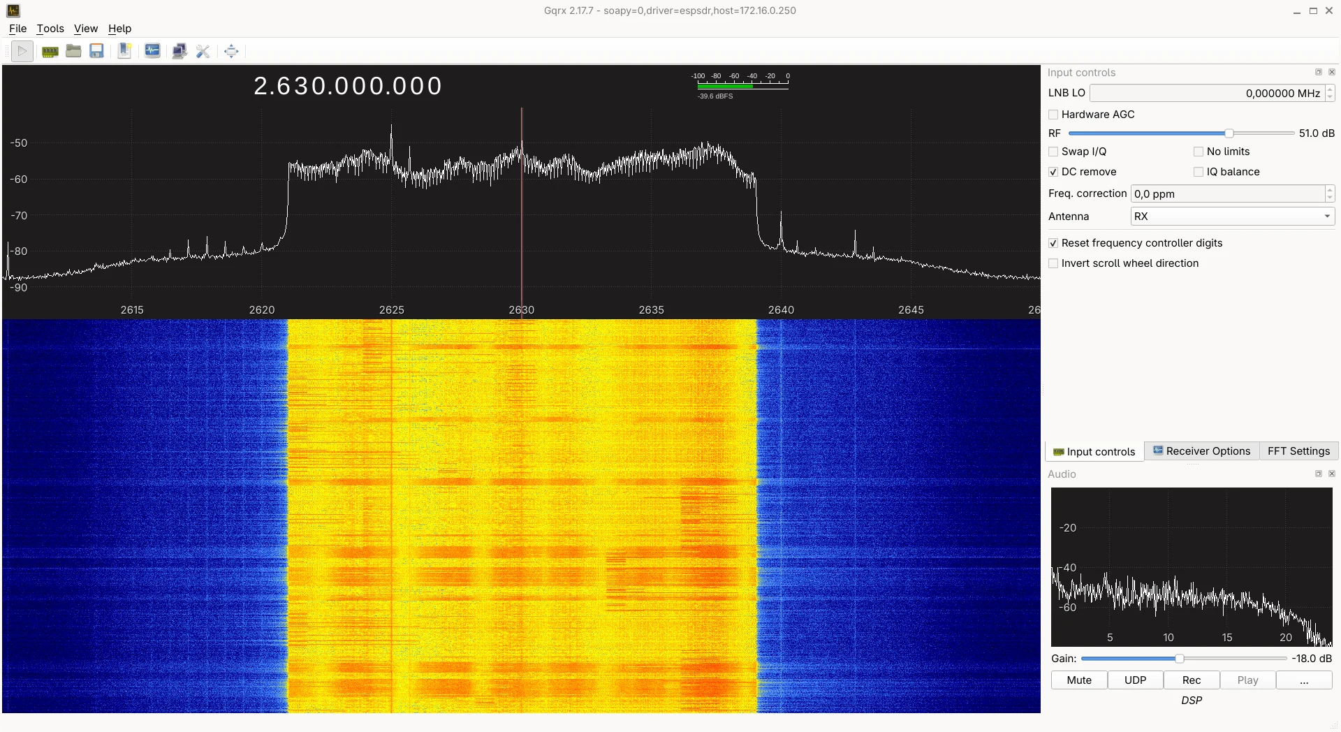
The experimental ESP32-S31 streaming architecture bypasses on-chip SRAM dump banks altogether. Instead, the receiver’s internal high-speed baseband debug lines are routed through the silicon’s GPIO Matrix and looped back internally into the PARLIO (Parallel IO) peripheral.
The PARLIO peripheral operates as an autonomous Direct Memory Access (DMA) engine, streaming 16-bit complex samples (8-bit I and 8-bit Q) directly into DMA buffers without CPU intervention. Over high-speed USB, this architecture sustains continuous 20 MS/s I/Q streaming. When paired with an onboard Gigabit Ethernet PHY, it achieves continuous 40 MS/s streaming into desktop Linux applications via SoapyESPSDR.
RF Frontend, Tuning Ranges, and Analog Filters
While Espressif rates its Wi-Fi radios strictly for the standard 2.4 GHz (2412 – 2484 MHz) and 5 GHz ISM allocations, the underlying Phase-Locked Loop (PLL) frequency synthesizers can tune substantially wider:
[ Tuning Range Coverage ]

1.85 GHz ─────────── 2.4 GHz ─────────── 2.65 GHz          5.15 GHz ─────────── 5.85 GHz
 ├─────────────────────┼────────────────────┤                ├─────────────────────┤
 │ Extended 5/6 LO     │ Native 2.4 GHz Band│                │ ESP32-C5 Dual-Band  │
 │ (Amateur 13cm, LTE) │ (Wi-Fi, BLE, Zigbee)                │ (5 GHz Wi-Fi / ISM) │
The 5/6 Local Oscillator (LO) Trick
The integer/fractional-N synthesizers in the ESP32, C2, C3, S2, and S3 are architected to deliver local oscillator signals in the 2.4 GHz range. Researchers discovered that manipulating internal divider registers can configure a 5/6 prescaler into the LO chain.
Drawing upon investigations from the open source eSpDR project by h0m3us3r, ESP-SDR enables tuning down to approximately 1.85 GHz on ESP32, C2, C3, S2, and S3 devices, and down to 1.95 GHz on the C6. This extension allows the ESP32 to receive signals well below the standard Wi-Fi band, including:
– 1.9 GHz DECT cordless communications.
– 2.1 GHz and 2.6 GHz LTE/5G cellular downlinks.
– The 2.3 GHz (13cm) amateur radio microwave allocation (2300 – 2450 MHz).
On the ESP32-C5, dual-band RF circuitry adds native coverage of the 5 GHz microwave spectrum (covering 5.15 GHz to 5.85 GHz), making it capable of analyzing Wi-Fi 5/6 channels, 5.8 GHz amateur wireless mesh links, and drone video downlinks.
Baseband Analog Filtering
To prevent strong out-of-band signals from driving the ADC into non-linear saturation, ESP-SDR dynamically tunes the on-chip baseband low-pass analog filters via the BBTOP block (0x67 over internal I2C host 1). The firmware adjusts internal capacitor banks to configure filter bandwidths between 12 MHz and 69 MHz on the ESP32-S3, and 4 MHz to 11 MHz on the ESP32-H2.
Managing AGC Behavior on Continuous Signals
The built-in hardware AGC in Espressif Wi-Fi chips is optimized to settle rapidly on short packet preambles (such as 802.11 OFDM training symbols). When exposed to strong, continuous RF carriers (such as an unmodulated CW carrier, an amateur FM signal, or a nearby test beacon), the hardware AGC frequently miscalculates the signal envelope, driving the ADC into hard clipping and generating intermodulation artifacts across the entire waterfall.
ESP-SDR addresses this by supporting manual gain calibration indices (GAIN <index>). When working with strong signals or conducting calibrated power measurements, operators should disable hardware AGC and lock the receiver to a fixed gain step.
Practical Amateur Radio and RF Engineering Applications
Transforming an everyday microcontroller into a software-defined receiver unlocks numerous real-world applications for radio amateurs, security researchers, and embedded developers:
1. 13cm (2.4 GHz) Amateur Radio Band Monitoring
The 2.4 GHz amateur radio band spans 2300 MHz to 2450 MHz in many international jurisdictions (and 2390 – 2450 MHz in Malaysia under MCMC allocations). Hams use this band for high-speed multimedia mesh networking (AREDN), digital amateur television (DATV), and satellite downlinks (such as the Es’hail-2 / QO-100 geostationary satellite uplink/downlink monitoring). An ESP32 running ESP-SDR acts as a dedicated, low-cost monitor for 13cm activity without tying up an expensive primary station SDR.
2. Drone Telemetry and FPV Video Detection
Unmanned aerial vehicles (drones) rely heavily on 2.4 GHz and 5.8 GHz frequency-hopping spread spectrum (FHSS) and OFDM links for control telemetry and analog/digital video transmission. With ESP-SDR running in high-speed waterfall mode, field technicians can immediately spot drone frequency hopping bursts and verify transmitter activity in sensitive airspace.
3. Spectral Cleanliness and Coexistence Testing
For IoT hardware developers designing products that combine Wi-Fi, Bluetooth, and custom sub-GHz protocols, ESP-SDR functions as an agile benchtop spectrum analyzer. It visualizes adjacent-channel splatter, harmonic radiation, and Bluetooth advertising congestion directly on a laptop screen using only a USB cable.
4. Downconverter Pairing for HF, VHF, and UHF
While ESP-SDR natively listens in the microwave spectrum, pairing an ESP32 receiver with an inexpensive active RF mixer or microwave downconverter transforms it into a general-coverage receiver. Feeding an intermediate frequency (IF) output of 1.9 GHz or 2.4 GHz into the ESP32 allows operators to digitize wide swaths of the 2m (144 MHz) or 70cm (430 MHz) amateur bands using the ESP32’s fast 80 MS/s digitizer.
Step-by-Step Setup: Flashing and Running ESP-SDR
Getting started with ESP-SDR requires zero toolchain compilation. Everything can be set up directly from a modern Chromium-based web browser supporting the Web Serial API (Google Chrome, Microsoft Edge, or Brave).
Step 1: Flashing Firmware via the Browser
- Connect your ESP32 board (an ESP32-S3 or ESP32-C3 board with a native USB port is recommended) to your computer using a data-capable USB-C cable.
- Navigate to the official Browser Firmware Installer.
- Select your connected USB serial port when prompted by the browser.
- Choose your chip model from the dropdown list and click Install ESP-SDR Firmware. The web flasher will automatically write the partition table, bootloader, and application binary to flash memory.
Step 2: Live Spectrum Analysis in the Browser
Once flashing is complete:
1. Open the Browser SDR Viewer.
2. Click Connect and select the ESP32 USB Serial port.
3. Set your desired center frequency (e.g., 2442 MHz for Wi-Fi Channel 7 or 2400 MHz for amateur microwave beacons).
4. Select your preferred sample rate (80, 40, or 16 MS/s) and FFT bin count (from 256 up to 2048 bins).
5. Watch the live real-time waterfall and spectrum display render directly in your browser.
Step 3: Desktop SDR Software Integration
To stream decimated I/Q data into desktop SDR applications on Linux or Windows:
- Clone and run the esp-sdr-bridge utility:
bash

git clone https://github.com/z2labs/esp-sdr-bridge.git

cd esp-sdr-bridge

python3 -m venv venv && source venv/bin/activate

pip install pyserial

python3 bridge.py --port /dev/ttyACM0 --rate 250000 - The bridge initiates continuous decimated I/Q capture and launches a local
rtl_tcpserver on127.0.0.1:1234. - Open your favorite SDR software (such as Gqrx, SDR++, or CubicSDR), select RTL-SDR Spectrum Server as your source, set the host address to
127.0.0.1port1234, and start streaming.
Hardware Tips and Common Pitfalls
Operating high-speed RF baseband capture on microcontrollers introduces several unique electrical and operating system quirks:
- Power Supply Current Spikes: The internal RF synthesizer and LNA draw sudden current surges when the receiver initializes. If you power an ESP32 through a low-grade USB-UART bridge’s onboard 3.3V LDO regulator, the voltage rail can sag below 2.8V, triggering a brownout reset loop. Always power boards from a dedicated, well-decoupled USB port or an external 5V power supply.
- Linux ModemManager Resets: On Linux distributions running
ModemManager, the daemon frequently detects newly connected Espressif USB Serial/JTAG devices and sends AT Hayes modem probes to identify them as cellular modems. This probe string will interrupt ESP-SDR binary synchronization. Disable ModemManager or add a udev rule to ignore Espressif Vendor IDs (303a). - UART Baud Rate Tolerances: For ESP32 boards lacking native USB (such as the original classic ESP32), the firmware defaults to a 2 Mbaud UART connection. Inexpensive CH340 or CP2102 clone chips frequently exhibit clock drift at 2 Mbaud, producing CRC32 checksum errors. If framing errors occur, use the viewer’s Switch to 1 Mbaud option.
Why ESP-SDR Matters for Open Source Radio
ESP-SDR demonstrates how creative software reverse-engineering can unlock profound new capabilities from commodity silicon. By transforming an undocumented RF test routine into a versatile software-defined radio receiver, the ESPARGOS team has put baseband signal analysis into the hands of anyone with a pocket-change microcontroller.
Whether you’re monitoring 2.4 GHz microwave amateur transmissions, investigating IoT protocol interference, or building distributed RF sensor networks, ESP-SDR offers a remarkable, zero-cost window into the radio spectrum.
Sources and Further Reading
- ESPARGOS ESP-SDR GitHub Repository: https://github.com/ESPARGOS/esp-sdr
- ESP-SDR Official Project Overview and Web Tools: https://espargos.net/espsdr/
- ESP-SDR Browser Firmware Flasher: https://espargos.net/espsdr/app/flash.html
- ESP-SDR Browser Spectrum Analyzer App: https://espargos.net/espsdr/app/
- SoapyESPSDR Hardware Driver: https://github.com/ESPARGOS/SoapyESPSDR
- esp-sdr-bridge by Z2Labs: https://github.com/z2labs/esp-sdr-bridge
- eSpDR by h0m3us3r (5/6 LO Research): https://github.com/h0m3us3r/eSpDR
- Espressif Systems ESP-IDF Documentation: https://docs.espressif.com/projects/esp-idf/
- ESPARGOS Antenna Array Systems: https://espargos.net/
73 de 9M2PJU.

Post Comment