Amateur Radio Field Battery Handling Guide: Terminal Connection Sequences, Safety, and DC Power Architecture
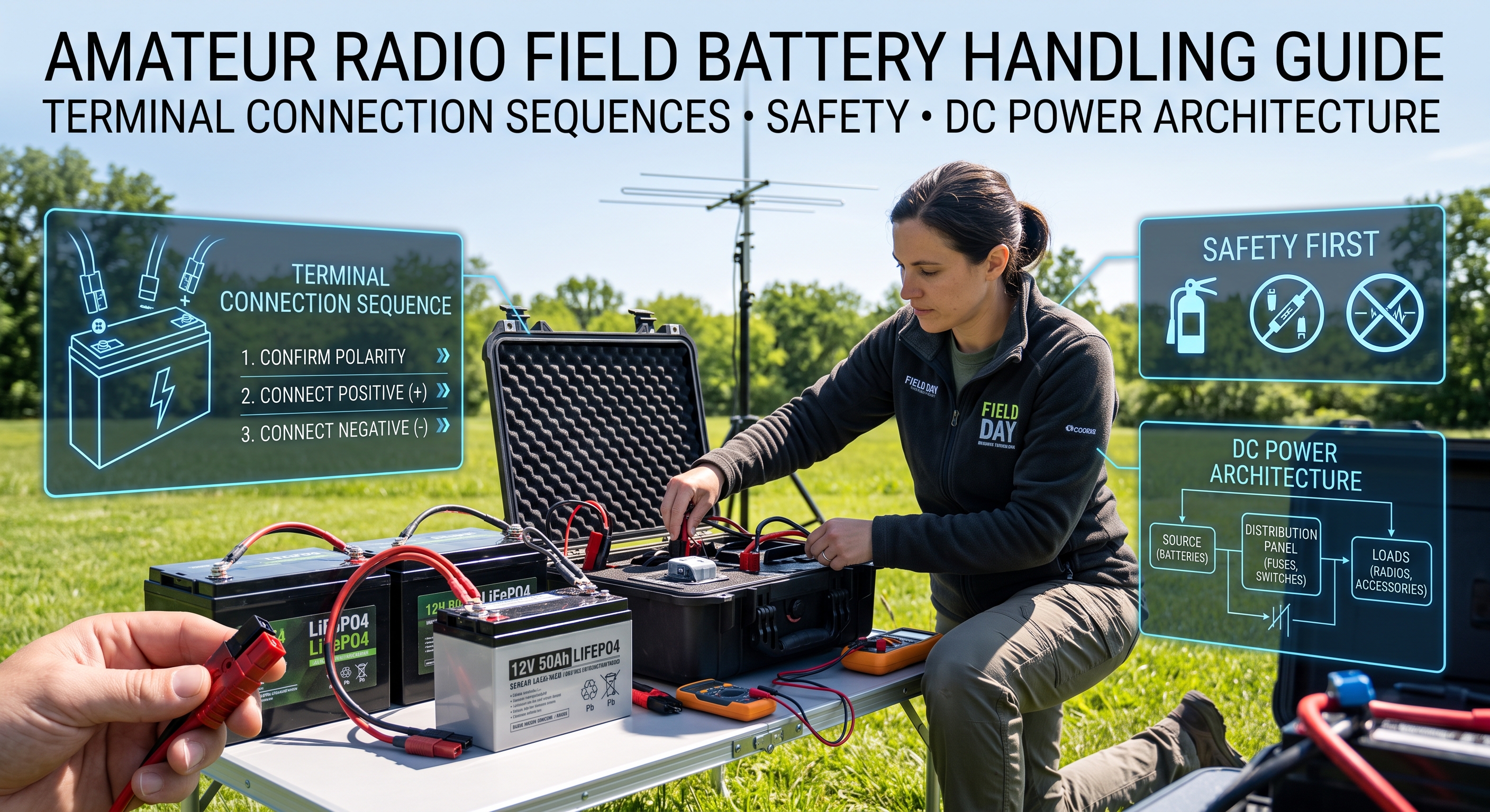
TL;DR: When installing equipment to a battery, always connect the Positive (+) terminal first and the Negative (-) terminal last. When unhooking or uninstalling equipment, reverse the sequence: disconnect the Negative (-) terminal first and the Positive (+) terminal last. In vehicle installations and grounded field stations, connecting positive first ensures that an accidental slip of a metal wrench against the chassis creates no short circuit. In portable multi-device setups, proper terminal sequencing and dedicated in-line fusing prevent destructive sneak ground loops from vaporizing USB controller chips and radio circuit board traces.
What is Field Battery Power Architecture in Amateur Radio?
Amateur radio field battery power architecture is the engineered deployment of portable direct-current (DC) power sources, safety disconnects, overcurrent protection devices, and standardized cabling to reliably energize transceivers and station accessories in off-grid environments.
+-----------------------------------------------------------------------------+
|               PORTABLE AMATEUR RADIO FIELD DC POWER ARCHITECTURE            |
+-----------------------------------------------------------------------------+
|                                                                             |
|  [ Solar Array / PV ] ---> [ MPPT Solar Charge Controller ]                 |
|                                         |                                   |
|                                         v                                   |
|  +-----------------------------------------------------------------------+  |
|  |                12.8V LiFePO4 Field Battery (4S Chemistry)             |  |
|  |  * High Instantaneous Discharge (>50A Peak)   * Internal BMS Board   |  |
|  +-----------------------------------+-----------------------------------+  |
|                                      |                                      |
|            [ Primary In-Line Fuse: 25A-30A ATC/ATO on Positive Lead ]       |
|                                      | (Distance <= 15 cm / 6 inches)       |
|                                      v                                      |
|  +-----------------------------------------------------------------------+  |
|  |           Inline Coulomb Counter / Digital DC Wattmeter               |  |
|  |           (Monitors Real-Time Voltage, Amps, Amp-Hours, Watt-Hours)   |  |
|  +-----------------------------------+-----------------------------------+  |
|                                      |                                      |
|                                      v                                      |
|  +-----------------------------------------------------------------------+  |
|  |               Fused DC Distribution Block (Anderson Powerpoles)       |  |
|  +-------+---------------------------+---------------------------+-------+  |
|          |                           |                           |          |
|          v                           v                           v          |
|   [ 100W HF Transceiver ]     [ Auto Antenna Tuner ]     [ Digirig / TNC ]  |
|   (20A-22A Peak Draw)         (1.5A Peak Draw)           (500mA USB Host)   |
|                                                                             |
+-----------------------------------------------------------------------------+
Whether activating a remote summit for Summits on the Air (SOTA), operating from a national park for Parks on the Air (POTA), establishing emergency communications (EmComm) during natural disasters, or setting up a multi-operator Field Day station, clean DC power is the foundation of every successful off-grid contact.
Operating portable introduces electrical hazards rarely encountered in the home shack. High-capacity field batteries, such as Lithium Iron Phosphate (LiFePO4) packs, store immense chemical energy in compact enclosures. With internal resistance measured in single-digit milliohms, a dead short across battery terminals can deliver hundreds of amperes in a fraction of a millisecond. Understanding the physics of terminal connections, ground return paths, and overcurrent protection keeps your equipment functional and prevents fires, burns, and equipment destruction in the field.
Portable Battery Chemistries: Technical Comparison for Ham Radio Operators
Modern portable amateur radio has shifted away from heavy lead-acid batteries to high-density lithium formulations. Selecting the appropriate chemistry requires balancing nominal voltage, weight, discharge voltage plateau, and thermal characteristics:
| Battery Chemistry | Nominal Voltage (Cell / Pack) | Usable Voltage Range (Pack) | Energy Density (Wh/kg) | Cycle Life (80% DoD) | Voltage Sag Under 20A Load | Field Safety & Environmental Considerations |
|---|---|---|---|---|---|---|
| LiFePO4 (Lithium Iron Phosphate – 4S) | 3.2V / 12.8V | 10.0V – 14.6V (Flat plateau @ 13.0V – 13.2V) | 90 – 130 Wh/kg | 2,000 – 5,000+ | Very Low (<0.4V sag @ 20A) | Inherently stable chemistry. Low thermal runaway risk. Cannot charge below 0 deg C without heating. |
| Li-ion NMC (3S Pack) | 3.7V / 11.1V | 9.0V – 12.6V (Rapid drop below 11.0V) | 150 – 220 Wh/kg | 500 – 1,000 | High (Drops below 10.5V, triggering radio low-voltage cutoff) | Ultra-lightweight, but nominal voltage is too low for full 100W HF output without a boost regulator. |
| Li-ion NMC (4S Pack) | 3.7V / 14.8V | 12.0V – 16.8V (Fully charged: 16.8V) | 150 – 220 Wh/kg | 500 – 1,000 | Moderate | 16.8V fully charged exceeds standard radio 13.8V (+/-15% max 15.87V) tolerance; requires a buck regulator. |
| Sealed Lead-Acid (SLA / AGM) | 2.0V / 12.0V | 10.5V – 13.8V (Linear decline under load) | 30 – 40 Wh/kg | 200 – 400 | Extreme (Peukert’s effect cuts usable capacity by 50% at 20A) | Heavy, rugged, and charges below freezing, but severe voltage sag reduces TX power and causes premature shutdown. |
| LTO (Lithium Titanate – 5S) | 2.4V / 12.0V | 9.0V – 14.0V | 50 – 80 Wh/kg | 15,000 – 30,000 | Ultra-Low | Extreme cycle life and operates down to -30 deg C, but lower energy density and higher cost. |
For standard 100W amateur transceivers (such as the Icom IC-7300, Yaesu FT-891, Yaesu FT-991A, or Elecraft KX3/K4), 4-cell Lithium Iron Phosphate (4S LiFePO4) is the industry benchmark. A 4S LiFePO4 pack delivers a nominal 12.8V to 13.2V across 85% of its discharge curve, matching the 13.8V DC (+/- 15%) input specification of amateur transceivers without requiring external voltage regulators.
Positive First or Negative First? The Physics and Engineering Behind Terminal Order
A fundamental question every field operator must answer when working with raw battery posts, wing nuts, or spade lugs is: Which terminal do I connect first during installation, and which terminal do I disconnect first during teardown?
The universal engineering rule across automotive, marine, aerospace, and amateur radio electrical systems is:
- Installation (Connecting): Connect POSITIVE (+) FIRST, then connect NEGATIVE (-) LAST.
- Uninstallation (Disconnecting): Disconnect NEGATIVE (-) FIRST, then disconnect POSITIVE (+) LAST.
+-----------------------------------------------------------------------------+
|                      BATTERY TERMINAL CONNECTION RULES                      |
+-----------------------------------------------------------------------------+
|                                                                             |
|   INSTALLATION SEQUENCE:                                                    |
|   [ Step 1: Connect POSITIVE (+) ]  =====>  [ Step 2: Connect NEGATIVE (-) ] |
|   (Tool slip to frame = No Circuit)         (Tool slip to frame = 0V Delta) |
|                                                                             |
|   UNINSTALLATION SEQUENCE:                                                  |
|   [ Step 1: Disconnect NEGATIVE (-) ] ===>  [ Step 2: Disconnect POSITIVE (+) ]
|   (Tool slip to frame = 0V Delta)           (Chassis already isolated)      |
|                                                                             |
+-----------------------------------------------------------------------------+
1. The Vehicle and Chassis-Grounded Field Setup
In mobile setups, recreational vehicles, or Field Day operations where the station ground is bonded to a vehicle frame or common metallic earth bus, the entire metal chassis of the vehicle is electrically connected to the battery’s negative terminal.
SCENARIO A: CONNECTING NEGATIVE FIRST (DANGEROUS MISTAKE)
-----------------------------------------------------------------------------
1. You connect the Negative (-) terminal to the battery.
   RESULT: The entire metal vehicle chassis is now LIVE NEGATIVE.
2. You take your metal wrench to tighten the Positive (+) terminal bolt.
3. The wrench slips and touches the bare vehicle body or mounting bracket.
   CONSEQUENCE: DEAD SHORT CIRCUIT!
   [ Battery (+) ] ===> [ Metal Wrench ] ===> [ Vehicle Frame ] ===> [ Battery (-) ]
   Current: 800A - 2,000A+
   Outcome: Arc flash, molten copper spray, wrench welded to frame, battery explosion!

SCENARIO B: CONNECTING POSITIVE FIRST (THE SAFE ENGINEERING STANDARD)
-----------------------------------------------------------------------------
1. You take your metal wrench to tighten the Positive (+) terminal bolt first.
2. The wrench slips and touches the bare vehicle body or mounting bracket.
   RESULT: NOTHING HAPPENS.
   Because the negative terminal is disconnected, there is no return path.
   The vehicle chassis is floating relative to the battery negative post.
3. You now take your wrench to tighten the Negative (-) terminal bolt.
4. If the wrench slips and touches the chassis, it connects Negative to Negative.
   RESULT: Zero volts potential difference (0V delta). No sparks, no current flow.
2. Standalone Portable Batteries and Sneak Ground Paths
Operators often assume that standalone portable batteries (such as an ammo-can LiFePO4 battery sitting on a wooden picnic table) do not have a metal chassis, so terminal order should not matter. This assumption is dangerous because of sneak ground loops.
In a typical field setup, multiple interconnected lines tie your equipment together:
- DC Power Cables: Supplying +13.8V and Ground.
- Coaxial Shield: Connecting transceiver ground to external antenna tuners, antennas, or grounded counterpoise wires.
- Data Cables: USB connections linking your radio’s internal digital interface or Digirig to a laptop, Raspberry Pi, or external sound card.
- Audio / PTT Patch Cords: Shielded leads running to keyers or voice processors.
+-------------------+                                  +-------------------+
|  Field Transceiver|                                  |   Field Laptop /  |
|  (IC-7300/FT-891) |<=========== USB Data Cable =====>|    Raspberry Pi   |
+---------+---------+    (Fine Shield / Signal GND)    +---------+---------+
          |                                                      |
    Heavy DC Cable                                         USB Host 5V/GND
   (10 AWG / 20A TX)                                             |
          |                                                      |
          v                                                      v
+---------+------------------------------------------------------+---------+
|                  COMMON PORTABLE BATTERY / DC SOURCE                     |
+--------------------------------------------------------------------------+
If you disconnect the heavy DC negative power lead while positive power and data cables remain attached, or if negative makes intermittent contact during installation, the radio’s DC return current will search for alternative return paths back to the battery or earth.
The transceiver’s 20-amp transmit return current will flow through the hair-thin copper braid of your USB cable, through the laptop’s motherboard ground planes, and out through auxiliary accessories. This instantaneous surge vaporizes USB PHY controller chips, melts printed circuit board traces, and destroys audio interface transformers.
By strictly adhering to the standard installation sequence (Positive first, Negative last) and teardown sequence (Negative first, Positive last), and ensuring master equipment power switches remain turned off during connection, you eliminate transient ground offsets and destructive surge paths.
Fusing Best Practices: Location, Sizing, and the Dual-Fuse Debate
A fuse does not exist primarily to protect your radio’s internal components from failing. A fuse exists to protect the DC power wiring and the battery from catching fire and melting during a short circuit.
+-----------------------------------------------------------------------------+
|                          PROPER IN-LINE FUSE PLACEMENT                      |
+-----------------------------------------------------------------------------+
|                                                                             |
|      [ Battery (+) Post ]                                                   |
|               |                                                             |
|               |  <=== Short Wire (<= 15 cm / 6 inches)                      |
|               v                                                             |
|     +-------------------+                                                   |
|     | In-Line Fuse (25A)|                                                   |
|     +---------+---------+                                                   |
|               |                                                             |
|               |  <=== Long Run (1.0m - 2.5m) to Radio / Power Distribution  |
|               v                                                             |
|      [ Radio / RigRunner ]                                                  |
|                                                                             |
+-----------------------------------------------------------------------------+
1. Fuse Placement Proximity
The in-line fuse holder on the positive lead must be located within 15 cm (6 inches) of the battery’s positive terminal.
If you place the fuse 2 meters down the cable near the radio, any pinch, abrasion, or insulation wear along the intervening 2 meters of wire creates an unfused direct short across the battery pack. A 4S LiFePO4 battery will dump over 100A through a pinched wire, melting PVC insulation into toxic fumes and igniting dry grass or tent fabric in under 3 seconds.
2. Sizing Fuses for Transmit Peaks
Fuses must be sized to handle the peak current of your transmitter without nuisance tripping, while remaining small enough to blow instantly during a hard short:
- 100W HF Transceiver (SSB / CW / Digital): Draws 18A to 22A at peak output. Install a 25A or 30A automotive blade fuse (ATC / ATO).
- 50W VHF/UHF Mobile Transceiver: Draws 8A to 12A at high power. Install a 15A fuse.
- 5W – 10W QRP Transceiver (Elecraft KX2, Lab599 TX-500, Xiegu G90): Draws 1.5A to 3.0A at peak output. Install a 5A fuse.
3. The Dual-Fusing (Positive & Negative) Debate
Most Japanese amateur radio mobile transceivers ship from the factory with twin fuse holders: one on the red positive lead and one on the black negative lead. Understanding why this is done clarifies how to handle portable field wiring:
- In Automotive Installations: Dual fusing protects the radio from vehicle ground failure. If the heavy copper ground strap between the vehicle’s engine block and chassis corrodes or snaps, the hundreds of amperes required by the starter motor will try to ground itself through the radio’s antenna shield, through the radio chassis, and down the radio’s black DC wire. The negative fuse blows immediately, saving the radio from turning into an engine ground jumper.
- In Portable Standalone Setups: A blown negative fuse in a portable multi-device station can create a sneak ground loop. If the negative DC fuse blows while the positive lead remains energized, the transceiver will route its negative return current through the USB braid of your attached laptop.
- Field Standard: Always maintain a primary fuse on the positive lead right at the battery terminal. If using a fused DC distribution block (like a RigRunner or Powerwerx box), individual equipment lines receive individual positive branch fuses.
Eliminating Bare Terminal Hazards: Anderson Powerpole Architecture
Exposed screw terminals, alligator clips, and automotive cigarette lighter plugs are among the most common points of failure in field operations. Alligator clips easily detach, short against adjacent metal, and introduce high resistance connections that cause significant voltage drop.
The worldwide standard for amateur radio DC power distribution is the Anderson Powerpole 15/30/45 series connector.
+-----------------------------------------------------------------------------+
|               ARES / ARRL STANDARD ANDERSON POWERPOLE PINOUT                |
+-----------------------------------------------------------------------------+
|                                                                             |
|                       +-------------+-------------+                         |
|                       |     RED     |    BLACK    |                         |
|                       |  (POSITIVE) |  (NEGATIVE) |                         |
|                       |     [ + ]   |    [ - ]    |                         |
|                       +-------------+-------------+                         |
|                                                                             |
|   Rule of Thumb: "RED on RIGHT, TONGUE on TOP"                              |
|   (Looking at the mating face with the contact hood pointing up)            |
|                                                                             |
+-----------------------------------------------------------------------------+
Advantages of Anderson Powerpoles in the Field
- Genderless Design: Any Powerpole cable can connect to any other Powerpole cable, simplifying field interconnections and emergency equipment sharing.
- Polarity Keying: Assembled according to the ARES standard (Red on Right, Black on Left with hood top), it is mechanically impossible to connect reverse polarity.
- Wiping Action Contacts: When inserted, the internal silver-plated copper contacts slide past each other under spring tension, cleaning oxidation and dirt off the contact surfaces on every mate.
- Finger-Safe Enclosure: The recessed internal contacts prevent accidental tool shorts or metal contact when cables are loose in a backpack or go-box.
Complete Step-by-Step Equipment Installation and Uninstallation Procedure
Follow this checklist to assemble and tear down your portable station safely:
+-----------------------------------------------------------------------------+
|                     FIELD DC POWER COMMISSIONING WORKFLOW                   |
+-----------------------------------------------------------------------------+
|                                                                             |
|  [ PRE-TRIP CHECK ]                                                         |
|  ├── Measure battery State of Charge (SoC) using a coulomb counter.         |
|  ├── Verify wire gauge: 10 AWG or 12 AWG for 100W HF rigs.                 |
|  └── Inspect in-line fuse condition and Powerpole pin retention.            |
|                                                                             |
|  [ STEP 1: VERIFY OFF STATE ]                                               |
|  └── Confirm all radio and accessory power switches are set to OFF.         |
|                                                                             |
|  [ STEP 2: CONNECT DC POWER (POSITIVE FIRST) ]                              |
|  ├── Bare Terminals: Connect POSITIVE (+) lead first; torque securely.      |
|  ├── Bare Terminals: Connect NEGATIVE (-) lead second.                      |
|  └── Powerpoles: Insert master battery cable into fused distribution block. |
|                                                                             |
|  [ STEP 3: CONNECT RF & DATA CABLING ]                                      |
|  ├── Attach antenna feedline (coax) and RF ground/counterpoise.             |
|  └── Attach USB/audio data lines to computer and station accessories.       |
|                                                                             |
|  [ STEP 4: POWER UP & OPERATE ]                                             |
|  ├── Turn on transceiver power switch.                                      |
|  └── Monitor voltage under transmit (verify sag remains < 0.5V).            |
|                                                                             |
|  [ TEARDOWN: REVERSE SEQUENCE ]                                             |
|  ├── 1. Turn OFF all equipment switches.                                   |
|  ├── 2. Disconnect data cables and antenna coaxial feedlines.               |
|  └── 3. Disconnect power: NEGATIVE (-) first, POSITIVE (+) last.            |
|                                                                             |
+-----------------------------------------------------------------------------+
Step 1: Pre-Trip Inspection and Sizing
- Verify Battery State of Charge (SoC): LiFePO4 batteries have an exceptionally flat discharge curve. A digital voltmeter reading 13.1V could mean 70% capacity or 30% capacity. Use a coulomb-counting inline wattmeter to verify true capacity before departing.
- Verify Wire Gauge: Minimize resistive DC voltage drop along cable runs. For a 100W transceiver drawing 20A over a 2-meter round-trip run, use 10 AWG or 12 AWG stranded copper wire.
Using undersized 18 AWG wire over a 2-meter run creates a voltage drop exceeding 0.85V during transmit, causing your radio to trigger premature low-voltage cutoffs during SSB voice peaks.
Step 2: Safe Installation Sequence (Connecting)
- Turn All Switches OFF: Never connect or disconnect DC cables while equipment is powered on. Hot-plugging under active load causes electrical arcing across connector pins, pitting contact surfaces and increasing contact resistance.
- Inspect Polarity and Fuses: Confirm Red matches Positive (+) and Black matches Negative (-). Verify the in-line fuse is firmly seated in its holder.
- If using Studs / Lugs / Terminals:
- Bolt the POSITIVE (+) red cable to the positive terminal first. Tighten securely and slide the insulating rubber boot over the terminal.
- Bolt the NEGATIVE (-) black cable to the negative terminal last. Tighten securely.
- If using Anderson Powerpoles / Distribution Block:
- Plug the master battery lead into the input of your fused distribution block (e.g., RigRunner or Powerwerx block).
- Verify output voltage on the distribution block’s digital voltmeter (13.0V – 13.4V for healthy LiFePO4).
- Plug individual radio and accessory leads into their respective fused output ports.
- Attach RF and Data Interconnects: Connect antenna coax, antenna tuner control lines, and ground/counterpoise wires before plugging in sensitive USB cables to your laptop.
Step 3: Safe Uninstallation Sequence (Tear-Down)
- Power Down All Equipment: Turn off the transceiver, tuner, and accessories using their front-panel power switches.
- Disconnect Data and RF Lines: Unplug USB cables, audio patch cables, and antenna coaxial connectors.
- Disconnect DC Power:
- If using bare posts/lugs: Unbolt the NEGATIVE (-) black cable first. Insulate the cable end. Unbolt the POSITIVE (+) red cable last.
- If using Anderson Powerpoles: Firmly grip the molded plastic housings of the connectors and pull straight apart. Never yank or pull on the copper wires, as this weakens the crimp joint inside the contact barrel.
- Cap and Insulate Battery Terminals: Install protective plastic caps or insulating tape over bare battery posts immediately to prevent accidental shorts from tent stakes, pack frames, or tools during transport.
Environmental Hazards: Temperature Extremes, Water, and Mechanical Shock
Deploying batteries outdoors exposes them to harsh environmental factors that degrade capacity or cause catastrophic failure if mismanaged.
+-----------------------------------------------------------------------------+
|                      ENVIRONMENTAL OPERATING BOUNDARIES                     |
+-----------------------------------------------------------------------------+
|                                                                             |
|  [ SUB-FREEZING ( < 0 deg C / 32 deg F ) ]                                  |
|  * DISCHARGING (Operating): SAFE down to -20 deg C (-4 deg F).              |
|  * CHARGING (Solar / Generator): FORBIDDEN! Causes Lithium Plating.         |
|                                                                             |
|  [ TROPICAL HEAT ( > 45 deg C / 113 deg F ) ]                               |
|  * Keep battery in shade; dark cases absorb solar infrared radiation.      |
|  * BMS thermal protection trips if internal cell temp exceeds 60 deg C.     |
|                                                                             |
|  [ MOISTURE & INGRESS ]                                                     |
|  * Condensation on terminals creates high-resistance galvanic corrosion.   |
|  * Store packs in IP65/IP67 rated ammo cans with sealed gland pass-throughs.|
|                                                                             |
+-----------------------------------------------------------------------------+
1. The Sub-Freezing Lithium Plating Hazard
While LiFePO4 batteries can safely discharge at temperatures down to -20 deg C (-4 deg F), you must never charge a standard LiFePO4 battery below 0 deg C (32 deg F).
Attempting to charge a frozen lithium cell prevents lithium ions from intercalating into the carbon anode structure. Instead, metallic lithium forms on the anode surface (a process called lithium plating). This causes permanent capacity loss, creates microscopic internal dendrites that puncture the separator film, and leads to internal short-circuits and fire. Ensure your field solar charge controller or battery BMS includes integrated low-temperature charge cutoff protection.
2. Tropical Heat and Solar Exposure
Direct sunlight on dark-colored battery cases can raise internal cell temperatures above 60 deg C (140 deg F). High temperatures accelerate electrolyte decomposition and trigger BMS thermal safety shutdowns mid-activation. Always keep your battery packs resting in the shade of a vehicle, beneath a solar panel, or inside an insulated field bag.
3. Transit and Airline Regulations (IATA)
When traveling by air for DXpeditions or remote activations:
- Lithium batteries must be transported in carry-on baggage only. They are strictly prohibited in checked luggage.
- Batteries under 100 Watt-hours (Wh) (e.g., a 12.8V 7.5Ah LiFePO4 pack = 96 Wh) can be carried without special airline authorization.
- Batteries between 100 Wh and 160 Wh (e.g., a 12.8V 12Ah pack = 153.6 Wh) require prior airline approval (typically limited to 2 spare units per passenger).
- Isolate all terminal contacts with non-conductive electrical tape or individual padded pouches to prevent terminal shorting in transit.
Frequently Asked Questions
Why should I always connect the positive terminal first on a battery?
Connecting the positive terminal first prevents dangerous short circuits. If your metal wrench touches the metallic vehicle chassis or station ground while tightening the positive post, no circuit exists because the negative lead is still disconnected.
What is the proper order when disconnecting equipment from a battery?
Always disconnect the negative terminal first, then disconnect the positive terminal last. Once the negative terminal is removed, the common chassis is electrically isolated, preventing sparks if a tool touches the frame while unhooking the positive lead.
Can I use alligator clips to connect my ham radio to a battery in the field?
No. Alligator clips provide high-resistance surface contact that creates significant voltage drop under heavy transmit loads. They easily detach, short against adjacent metal, and pose a severe fire hazard in field environments.
Why is LiFePO4 preferred over standard Lithium-ion for portable ham radio?
4S LiFePO4 delivers a flat 12.8V to 13.2V discharge plateau that matches standard 13.8V transceiver specifications without voltage converters. Standard 3S Li-ion voltage drops too low under load, while 4S Li-ion exceeds safe radio voltage limits.
Can I charge a LiFePO4 battery in sub-freezing temperatures?
No. Charging standard LiFePO4 below 0 deg C (32 deg F) causes irreversible lithium plating on the anode, permanently destroying cell capacity and creating severe internal short-circuit hazards. Always warm the pack above freezing before charging.
Sources and Further Reading
- ARRL: Anderson Powerpole Standard Guidelines
- Powerwerx: DC Power Distribution and Fusing Engineering
- Bioenno Power: LiFePO4 Battery Characteristics for Amateur Radio
- West Mountain Radio: DC Power Safety and RigRunner Architecture
- IATA Lithium Battery Guidance Regulations
73 de 9M2PJU





1 comment