The Best NEC2 Antenna Simulator for Linux
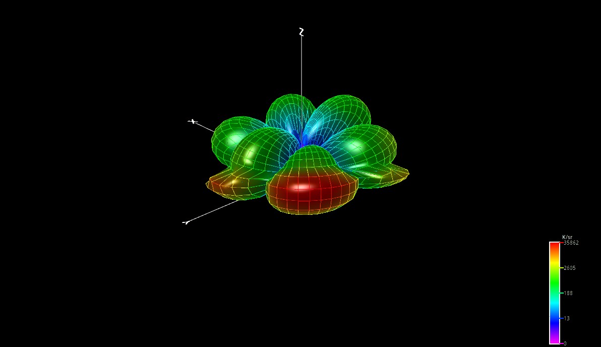
If you do antenna modeling on Linux, xnec2c is the tool to know. It is a graphical, multi-threaded NEC2 electromagnetic simulator that takes the classic FORTRAN NEC2 engine and wraps it in a modern, interactive GTK3 interface. No output files to parse. No batch-mode guesswork. You see radiation patterns, gain plots, and impedance data in real time, and you interact with them directly.
This article covers what xnec2c is, why it stands apart from other NEC2 implementations, and what it can do for your antenna work.
Background
NEC2, the Numerical Electromagnetics Code, was developed at Lawrence Livermore National Laboratory and has been the industry-standard antenna modeling engine for decades. The original code is FORTRAN. Neoklis Kyriazis, 5B4AZ, translated it to C as nec2c, a command-line tool. He then built xnec2c on top of that: a full graphical interface that replaced batch execution with interactive, on-demand calculation.
Maintenance of xnec2c has since passed to Eric Wheeler, KJ7LNW, and the project is actively developed on GitHub. The current release is version 4.5.0, a substantial update that added hardware-accelerated OpenGL rendering, a built-in antenna geometry optimizer, parametric modeling through symbolic variables, and noise temperature analysis.
Installation
Binary packages are available for the two most common non-Linux platforms:
- Linux via Flathub:
flatpak install flathub org.xnec2c.Xnec2c - macOS via MacPorts:
sudo port install xnec2c
To build from source on Debian or Ubuntu:
sudo apt-get install build-essential autoconf libtool gnome-devel libgsl-dev \
  libgtk-3-dev gettext autopoint gnome-icon-theme desktop-file-utils \
  libepoxy-dev libgl-dev

git clone https://github.com/KJ7LNW/xnec2c.git
cd xnec2c
./autogen.sh
./configure
make && sudo make install
sudo make desktop-install   # adds icons and .nec file association
For Rocky Linux, AlmaLinux, RHEL, or CentOS, substitute yum install gcc make automake autoconf gsl-devel gtk3-devel gettext-devel libtool libepoxy-devel mesa-libGL-devel.
What Makes It Different
Interactive, Not Batch
Classic NEC2 and nec2c work in batch mode: you write an input file, run the program, and parse a text output file. Xnec2c eliminates that cycle. You open a .nec file and get a live structure rendering. Open the Radiation Pattern window and click Gain. Open the Frequency Plots window and click Play. Everything calculates on demand and redraws immediately. Click anywhere on a frequency plot to jump to that frequency, and every window updates.
Multi-threaded Frequency Sweeps
For frequency sweeps, xnec2c forks child processes, one per CPU core, and distributes frequency steps across them in parallel. Launch it with -j8 on an 8-core machine and the sweep runs close to eight times faster than single-threaded. The GUI stays responsive throughout because only the parent process handles GTK.
Accelerated Math Libraries
Since version 4.3, xnec2c auto-detects ATLAS, OpenBLAS, and Intel MKL at runtime. If any of these accelerated BLAS libraries are installed, xnec2c uses them for the Gaussian elimination at the core of NEC2’s moment-method solver. The speedup is significant on larger antenna models with many segments.
OpenGL Rendering
Version 4.5.0 added a hardware-accelerated 3D renderer for both the structure display and the radiation pattern window. Wire segments render as lit 3D cylinders, patch surfaces as smooth triangulated meshes, and radiation patterns with full surface or wireframe draw styles. Multi-sample anti-aliasing is configurable from 2x to 16x. If OpenGL initialisation fails, xnec2c falls back to the original Cairo software renderer automatically.
Key Features
Radiation Pattern Visualization
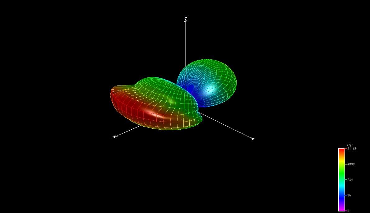
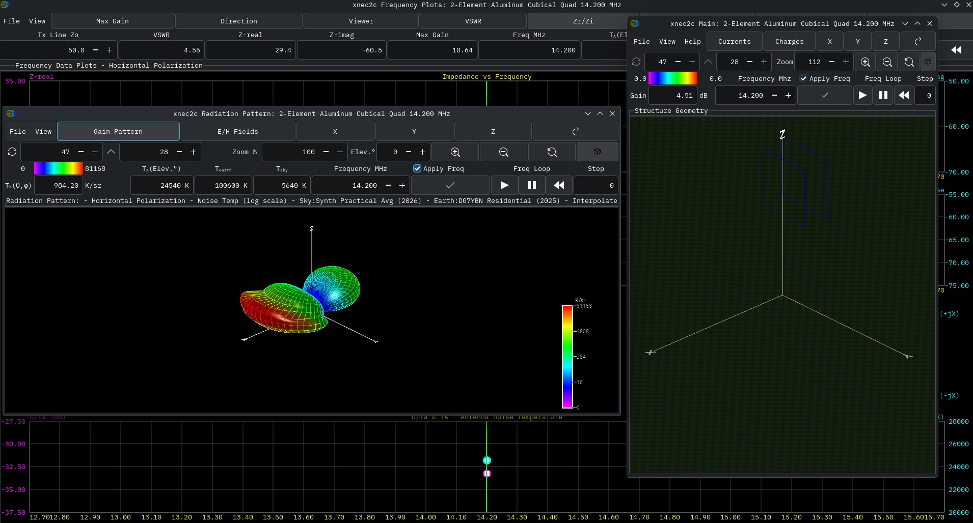
The Radiation Pattern window renders 3D gain patterns with color coding from maximum to minimum. Three draw styles are available: Surface (filled mesh), Wireframe, and Both. Gain scaling options include Linear Power, Linear Voltage, ARRL Style, and Logarithmic, each suited to different presentation needs. Near-field E/H patterns and Poynting vectors can also be rendered, with an animation mode to visualize field oscillation at a selectable frame rate.
Frequency Data Plots
The Frequency Plots window graphs any combination of these parameters against the sweep frequency range:
- Maximum gain and front-to-back ratio
- VSWR for a user-specified reference impedance (default 50 ohms)
- Input impedance, real and imaginary parts
- Impedance magnitude and phase
- S11 return loss
- Gain in the viewer direction
- Net gain (gain corrected for mismatch loss)
- Antenna temperature and G/T_ant
Clicking anywhere in the plot area immediately recalculates all data at that frequency.
Touchstone File Export
Frequency sweep results can be exported as S1P and S2P Touchstone files from the File menu. S11 is the feed-point return loss. S21 and S12 carry the antenna gain (either maximum gain or viewer gain, selectable). These files can be used directly in RF design software such as Microwave Office or Sonnet for matching network design.
Built-in NEC2 Editor
Xnec2c includes a full NEC2 input file editor with dedicated sub-editors for each card type: wire geometry (GW), helix (GH), arc (GA), excitation (EX), loading (LD), ground (GN), frequency range (FR), and radiation pattern (RP), among others. You do not need to know raw NEC2 card formats to use it. Edit, save, and the model reloads without closing the radiation pattern or frequency plot windows, so the edit-simulate-inspect cycle stays fast.
Symbolic Variables and Parametric Modeling
Xnec2c supports SY cards, compatible with 4nec2, for parametric antenna modeling. Instead of hard-coded dimensions, you define named variables and expressions:
SY FREQ=146, C=299.792458, LAMBDA=C/FREQ
SY L_DRV=0.468*LAMBDA, RADIUS=AWG_10
GW 2 25 0 L_DRV/2 0 0 -L_DRV/2 0 RADIUS
FR 0 21 0 0 FREQ-5 0.5
Change FREQ and every dimension derived from it updates automatically. The Symbol Overrides window exposes all named variables with sliders, min/max bounds, and an auto-apply mode that recalculates the full sweep after each adjustment with a 300 ms debounce. This turns xnec2c into a real-time antenna tuning console.
Predefined constants include PI, unit conversions (MM, CM, IN, FT), and AWG wire radii from AWG_0 through AWG_20.
Antenna Geometry Optimizer
Version 4.5.0 introduced a built-in optimizer. Variables marked for optimization in the Symbol Overrides window define the search dimensions. Min/max bounds define the search space. User-configured fitness goals specify what to optimize and how.
Two algorithms are available:
Particle Swarm (PSO) distributes a swarm of candidate solutions across the search space and converges toward the best-found region. Good for initial broad exploration. Configurable swarm size, neighborhood size, inertia, and search radius.
Nelder-Mead Simplex refines a solution already near a good region through geometric reflection and contraction. Best used after a PSO pass to descend precisely into the nearest minimum.
Fitness goals are fully configurable. Each goal specifies a measurement (VSWR, Max Gain, F/B Ratio, G/T_ant, beam direction deviation, impedance, and others), a direction (minimize, maximize, or converge to target), a target value, a weighting, a penalty exponent, a reduction method across frequencies (sum, average, worst-case, best-case), and an optional frequency band filter. The optimizer locks the frequency controls during a run and draws plot traces in dark green to indicate it is in control.
Optimizer settings persist in a .opt file alongside the .nec file and reload automatically on next open. Batch-mode optimization is supported via --batch --optimize command-line flags with --write-csv, --write-s1p, or --write-s2p-max-gain for automated output.
Noise Temperature Analysis
Xnec2c can evaluate antenna temperature, a key figure of merit for weak-signal work on VHF and UHF. The radiation pattern window renders each solid-angle cell by its gain-weighted brightness temperature in K/sr under a selectable RF noise environment. The Frequency Plots window shows T_ant, T_total, and G/T_ant across the operating band.
Sky and earth noise models are independent and selectable:
Sky models include G4CQM Min Quiet, VK3UM Min Quiet, the ITU-R P.372 galactic formula (continuous), DG7YBN Galactic Avg (used in the VE7BQH antenna comparison tables), and two synthesized practical-average models covering the full VHF/UHF range.
Earth models include the four ITU-R man-made noise formulas (Business, Residential, Rural, Quiet Rural), tabulated DG7YBN values (Rural, Residential, City), and the G4CQM and VE7BQH historical reference sets.
To reproduce published VE7BQH G/T antenna comparison table values, select DG7YBN Galactic Avg sky with the matching DG7YBN earth model. For broadband antenna development with smooth frequency coverage, the Synth Practical Avg sky paired with an ITU-R earth model covers the full VHF/UHF range continuously.
An elevation control in the toolbar sets the observation elevation angle. The sky/earth boundary remains at the geometric horizon while the pattern tilts, so cells pointing above the horizon see sky noise and those pointing below see earth noise. T_ant and G/T_ant can be added as fitness goals in the optimizer for noise-optimized antenna design.
Getting Started Quickly
- Launch xnec2c and open one of the bundled examples:
examples/2m_yagi.necrenders quickly and is a good starting point. - Select View → Radiation Pattern and View → Frequency Plots to open both output windows.
- In the Frequency Plots window, enable Max Gain and VSWR, then click the Play button to run the sweep.
- Click anywhere in the frequency plot to select a frequency. The radiation pattern and all data update immediately.
- Drag the radiation pattern with the mouse to rotate it. Use Ctrl+Scroll to adjust wire cylinder thickness.
For multi-core machines, always launch with the -j flag matching your CPU count:
xnec2c -j8 examples/2m_yagi.nec
External Optimizer Support
For custom optimization workflows, xnec2c monitors the open .nec file with inotify and reruns the frequency sweep whenever the file changes. An external program can read the results from a .csv file written by xnec2c, modify the .nec file with new parameters, and let xnec2c recalculate. Two external optimizer packages are available for this approach: xnec2c-gao (Haskell, genetic algorithm, by DC1MDP) and xnec2c-optimize (Perl, by KJ7LNW).
Supported Platforms
Xnec2c builds and runs on Linux, macOS (via MacPorts), FreeBSD, OpenBSD, and other UNIX-like systems. It supports 42 languages via GNU gettext, selected automatically from the system locale. The LANGUAGE environment variable overrides the locale if needed.
Project
Xnec2c is free software, licensed under GPL. The project is hosted at github.com/KJ7LNW/xnec2c and the official documentation is at xnec2c.org. Bug reports and pull requests are welcome.
For Malaysian amateurs, the software pairs naturally with any antenna work on VHF/UHF bands. The noise temperature analysis with G/T_ant output is directly relevant to anyone working EME, satellite, or weak-signal SSB/CW on the 2m and 70cm bands.



Post Comment