Hear the Invisible: Exploring Electromagnetic Fields with the SporkLogic EMF Explorer Badge
TL;DR: Quick Summary
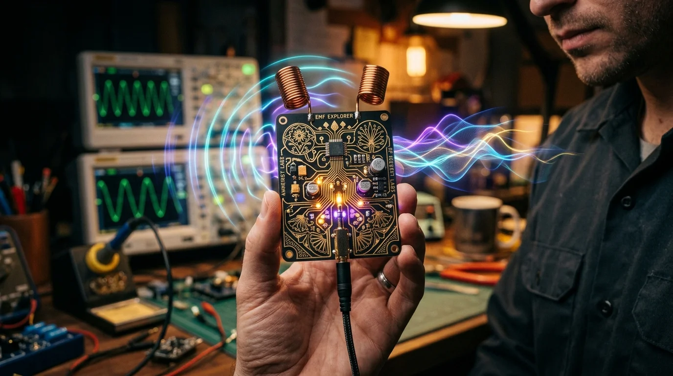
The SporkLogic EMF Explorer Badge, designed by artist and hardware engineer Darcy Neal, is an open-hardware, wearable electromagnetic sensing kit that transforms parasitic electromagnetic radiation from everyday electronics into audible sound. Utilizing dual inductors as magnetic pickup coils, a high-gain audio amplifier (~1000x boost), and a 3.5mm headphone jack, the badge allows makers, educators, and radio amateurs to listen directly to the switching frequencies, data bursts, and PWM modulations of computers, phones, motors, and power supplies. The board is also a wearable tech art piece featuring detailed KiCad vector artwork, illuminated rear LEDs, and an open design featured in Make: Magazine Volume 90.
What Is the SporkLogic EMF Explorer Badge?
The SporkLogic EMF Explorer Badge is a wearable electronic sensor board that uses inductive pickup coils and high-gain audio amplification to convert invisible near-field electromagnetic emissions from electronics into real-time audible frequencies through headphones.
Every electronic device in modern civilization produces an invisible electromagnetic aura. Switching power supplies oscillate at tens of kilohertz, microprocessor memory buses cycle with rapid burst activity, laptop trackpads emit capacitive touch pulses, and cellular modems negotiate towers with periodic RF bursts. Because human ears can’t perceive alternating magnetic fields directly, this entire electromagnetic landscape remains hidden from everyday perception.
Hardware designer and multimedia artist Darcy Neal created the SporkLogic EMF Explorer Badge to bridge this sensory divide. What started as hands-on hardware hacking workshops at gatherings like ToorCamp and hackerspaces has grown into a widely acclaimed STEM kit, featured prominently in Make: Magazine Volume 90 (“Electromagnetic Symphony: Explore the EMF Universe”) and available through the Maker Shed.
+-----------------------------------------------------------------------------------+
|                     EMF EXPLORER BADGE SIGNAL CONVERSION FLOW                     |
+-----------------------------------------------------------------------------------+

 NEARBY EMITTING ELECTRONIC DEVICE
 (Laptop, Charger, Phone, Motor, Inverter)
                  |
                  | [Changing Near-Field Magnetic Flux: 20 Hz - 20 kHz]
                  v
 +--------------------------------------------------+
 | INDUCTIVE SENSING STAGE                          |
 | Dual Board-Mounted Wire-Wound Inductors          |
 | (Faraday's Law: dPhi/dt induces micro-volt AC)   |
 +------------------------+-------------------------+
                          |
                          v
 +--------------------------------------------------+
 | HIGH-GAIN ANALOG AMPLIFICATION STAGE             |
 | Low-Noise Audio Op-Amp Circuit (~1000x Gain)     |
 | Powered by 2x AAA Alkaline Batteries (3.0V DC)   |
 +------------------------+-------------------------+
                          |
                          v
 +--------------------------------------------------+
 | 3.5mm STEREO AUDIO OUTPUT & HEADPHONES           |
 | Real-Time Audible Electroacoustic Signatures     |
 | (Transformer hums, PWM buzzes, data chatter)     |
 +--------------------------------------------------+
How Inductive EMF Sensing Works: The Physics Behind the Sound
To understand how the badge operates, one doesn’t need complex software defined radio algorithms. The circuit relies on fundamental electromagnetic principles first articulated by Michael Faraday in 1831:
1. Faraday’s Law of Induction
Whenever an electrical current changes within a circuit, it generates a proportional magnetic field around the conductor. If that magnetic field fluctuates across a nearby coil of wire (an inductor), it induces a corresponding electric voltage across the coil terminals:
$$\mathcal{E} = -N \frac{d\Phi_B}{dt}$$
Where:
– $\mathcal{E}$ is the induced electromotive force (voltage).
– $N$ is the number of wire turns in the inductor.
– $\frac{d\Phi_B}{dt}$ is the rate of change of the magnetic flux.
Every time a laptop screen refreshes, a phone flashes its camera strobe, or an electric scooter controller modulates motor current, rapid electrical transients ripple through nearby space.
2. High-Gain Audio Amplification (~1000x)
The micro-volt signals picked up by the badge’s inductors are far too weak to drive a set of headphones directly. The badge routes these weak signals through a high-gain, low-noise analog amplifier stage powered by two standard AAA batteries (3.0 V). Boosting the signal by roughly 1000 times brings weak parasitic currents up to standard line/headphone listening levels.
3. The Audio Band Window (20 Hz to 20 kHz)
Human hearing spans roughly 20 Hz to 20,000 Hz. Conveniently, many common electronic switching frequencies, clock prescalers, power supply harmonics, and motor PWM frequencies fall squarely within this audio band. The badge doesn’t downconvert or demodulate RF carriers. It directly amplifies the baseband audio magnetic fluctuations produced by internal circuitry.
The Artistic Engineering of the Badge
Beyond its utility as an electromagnetic listening probe, the EMF Explorer Badge is a striking example of modern PCB art:
- Vector Artwork in KiCad: Designed by Darcy Neal using KiCad, the badge’s flowing organic silkscreen and exposed copper traces were originally illustrated in Affinity Designer. They were then translated into copper, soldermask, and silkscreen layers using Gingerbread.
- Illuminated Backlighting: Several onboard LEDs cast a warm glow through the translucent FR-4 fiberglass substrate, illuminating the detailed copper veins from behind. Worn on a lanyard at night, the badge doubles as wearable illuminated cybernetic jewelry.
- Open-Source Hardware: Darcy Neal published the KiCad schematic and board layout on GitHub at drc3p0/emf-explorer-badge.
What Does the Electronic World Sound Like?
Plugging headphones into the badge reveals a surreal sonic environment. Different electronic components produce distinct acoustic signatures:
- Switching Power Supplies & Wall Warts: Produce high-pitched, singing whines or clicking pulses. Under varying current loads, the pitch slides up and down like a theremin.
- Light Dimmers & Motor Speed Controllers: Emit a loud, harsh 100 Hz or 120 Hz buzzing rasp caused by rapid triac phase chopping.
- Laptop Trackpads: As your finger glides across a capacitive touch sensor, you hear rapid rhythmic clicking and chirping as capacitive measurement cycles ramp up.
- Smartphones & Cellular Modems: Every few seconds, the phone negotiates network towers, creating distinctive bursts of rhythmic “dit-dit-dit… da-da-da” packet chatter.
- Bluetooth Headphones: Emits regular chirps and frequency-hopping bursts as devices ping beacons and exchange audio packets.
- Electric Scooters & Micromobility Motors: The regenerative brakes and brushless motor drivers generate aggressive variable-frequency synthesizer sweeps.
Video Walkthrough: Listening to EMF at the Hackerspace
Watch Darcy Neal take the EMF Explorer Badge on a listening tour through a lively hackerspace, capturing the hidden voices of 3D printers, monitors, power supplies, and electronics:
Technology Comparison: EMF Explorer Badge vs Other Detection Tools
| Feature / Metric | SporkLogic EMF Explorer Badge | Commercial Gaussmeter (Tri-Field) | RTL-SDR Software Defined Radio | AM Radio Sniffer (Transistor Radio) |
| :— | :— | :— | :— | :— | :— |
| Primary Purpose | Real-time audio exploration & art | Quantitative EMF field measurement | Wideband RF spectrum reception | Broadband RFI hunting |
| Detection Method | Dual wire-wound inductive coils | Tri-axial magnetic/electric sensors | Antenna input into SDR mixer/ADC | Ferrite bar antenna into RF mixer |
| Frequency Range | 20 Hz to 20 kHz (Acoustic baseband) | 40 Hz to 100 kHz (Field intensity) | 500 kHz to 1.7 GHz (Radio frequencies)| 530 kHz to 1700 kHz (Medium Wave) |
| Output Type | Direct 3.5mm stereo audio | LCD digital readout (mG or V/m) | Spectrum waterfall / demodulated audio| Internal speaker audio |
| Form Factor | Wearable lanyard PCB art badge | Handheld meter enclosure | USB dongle + computer / phone | Handheld portable radio |
| Assembly Required | Through-hole soldering kit | Fully assembled commercial unit | Fully assembled commercial unit | Fully assembled commercial unit |
| Wearable Tech Art | Yes (Illuminated back-lit LEDs) | No | No | No |
| Open Source | Yes (KiCad files on GitHub) | No (Proprietary) | Open source software drivers | No (Proprietary) |
Why Amateur Radio Operators and Makers Should Care
For radio amateurs, background electromagnetic noise (QRN and man-made RFI) is the arch-nemesis of weak-signal HF, VHF, and satellite reception.
A rogue LED bulb driver, failing solar inverter, noisy USB hub, or cheap wall adapter can blanket entire amateur bands with high-decibel hash, destroying your ability to hear distant DX stations.
The EMF Explorer Badge serves as an intuitive near-field “RFI sniffer.” By sweeping the badge along power cables, breaker boxes, computer desks, and charging bricks, an operator can pinpoint the exact component spewing electromagnetic trash in seconds.
For STEM educators and parents, the kit is an approachable soldering project for teens and beginners. Assembling the through-hole resistors, capacitors, inductors, audio jack, and battery clips teaches essential soldering fundamentals, while the immediate auditory payoff rewards curious exploration.
How to Get Started and Build the Badge
The kit is designed for beginners and intermediate makers:
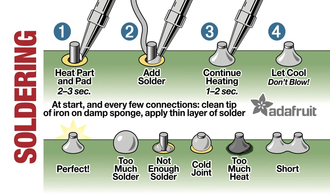
1. Gather Supplies: A standard 40W to 80W soldering iron, lead-free or 60/40 solder, wire snips, safety glasses, two AAA batteries, and 3.5mm stereo headphones.
2. Follow the Visual Guide: The board features clear silkscreen markings with color-coded component placements. Solder lower-profile resistors and diodes first, followed by capacitors, inductors, battery clips, and the audio jack.
3. Power On and Explore: Insert two AAA batteries, plug in your headphones, and bring the top inductors within inches of a phone, laptop keyboard, or power strip.
You can order the complete soldering kit directly from the Maker Shed or visit SporkLogic for workshop dates and documentation.
Frequently Asked Questions (FAQ)
What is the SporkLogic EMF Explorer Badge?
It’s a wearable open-source PCB badge designed by Darcy Neal that converts invisible electromagnetic radiation from electronics into audible sound through headphones.
Does the badge measure electromagnetic field strength in numbers?
No. Unlike a digital gaussmeter, it provides real-time acoustic feedback, letting you hear the unique tonal signatures of operating electronics.
Is soldering required to assemble the EMF Explorer Badge?
Yes. The badge is a through-hole soldering kit requiring basic soldering tools, wire snips, and adult supervision for younger builders.
What batteries does the badge use?
The badge operates on two standard AAA batteries (3.0 V DC total), providing hours of continuous listening and LED illumination.
Where can I find the schematic and KiCad design files?
The complete hardware schematics and KiCad board files are published openly on GitHub under Darcy Neal’s repository at drc3p0/emf-explorer-badge.
Sources and Further Reading
- SporkLogic Official EMF Explorer Badge Page – Project overview, documentation, and photo galleries.
- SporkLogic EMF Explorer Board Assembly Guide – Step-by-step soldering tutorial and safety instructions.
- EMF Explorer Badge GitHub Repository – Official KiCad board layout, schematic, and artwork files.
- Make: Magazine Volume 90: Electromagnetic Symphony – Featured article exploring the EMF universe with Darcy Neal.
- Maker Shed Store: EMF Explorer Badge – Official soldering kit distributor.
- YouTube: Listening to EMF at the Hackerspace – Video demonstration by Darcy Neal.
73 de 9M2PJU







Post Comment