BQ Voyage Station G3: The Modular 5-Watt LoRa & Meshtastic Base Station with Raspberry Pi Header and Dynamic LNA
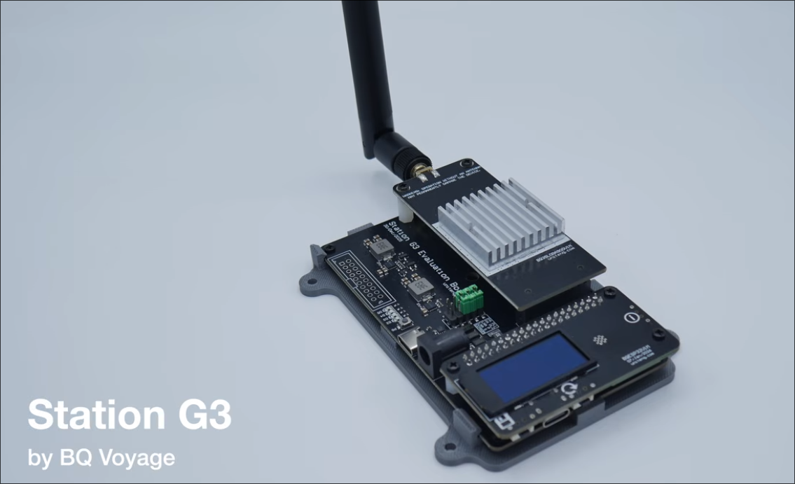
TL;DR: The Station G3 by BQ Voyage is a modular, high-power LoRa development platform and base station node engineered for Meshtastic, Meshcore, and custom Linux mesh networking. Built around a 3-part modular architecture (Motherboard, RF daughterboard, and MCU daughterboard), it features a standard Raspberry Pi 40-pin GPIO socket supporting both an ESP32-S3 module and a Raspberry Pi Zero 2W. With an internal Power Amplifier delivering up to 37 dBm (~5 Watts), an active Low Noise Amplifier (LNA) with dynamic gain control, Fast-Transient DC-DC power delivery, and onboard INA219 power telemetry, the Station G3 sets a new standard for high-performance off-grid mesh infrastructure.
What is the Station G3?
The BQ Voyage Station G3 is a modular amateur radio and IoT base station platform that combines a high-power LoRa transceiver, dynamic receiver front-end, and a Raspberry Pi compatible 40-pin MCU socket into a single development board.
+-------------------------------------------------------------------------+
|                         BQ Voyage Station G3                            |
|                                                                         |
|  +-------------------------------------------------------------------+  |
|  |                  MCU Daughterboard (Socket No. 1)                 |  |
|  |   [Option A: BQESP32V1M]           [Option B: Raspberry Pi Zero]  |  |
|  |   ESP32-S3 (16MB Flash, 8MB PSRAM)  Linux Native (meshtasticd /   |  |
|  |   1.3-inch OLED Display             mPWRD-OS Armbian Daemon)      |  |
|  +---------------------------------+---------------------------------+  |
|                                    | (40-Pin Raspberry Pi Header)       |
|                                    v                                    |
|  +-------------------------------------------------------------------+  |
|  |                        Station G3 Motherboard                     |  |
|  |  * Fast-Transient DC-DC Power Delivery Engine                     |  |
|  |  * 15V USB-C PD or 9V-19V DC5521 Input (>= 25W)                   |  |
|  |  * INA219 Voltage & Current Telemetry Sensor                      |  |
|  |  * Power Good Checker (4 Diagnostic Status LEDs: D2, D3, D4, D5)  |  |
|  |  * Hardware Configuration Jumpers (PA PL1, PA PL2, LNA P)         |  |
|  +---------------------------------+---------------------------------+  |
|                                    |                                    |
|                                    v                                    |
|  +-------------------------------------------------------------------+  |
|  |             RF Daughterboard: BQ35LORA900V1M (Primary Slot)       |  |
|  |  * Semtech SX1262 LoRa Transceiver (850 MHz - 930 MHz)            |  |
|  |  * Multi-Stage Power Amplifier (4 Power Levels up to 37 dBm / 5W) |  |
|  |  * Active LNA with Dynamic Gain Control & Dynamic Impedance Match |  |
|  +---------------------------------+---------------------------------+  |
+------------------------------------|------------------------------------+
                                     |
                                     v
                          [LoRa Antenna / SMA Port]
                           (868 MHz EU / 915 MHz US)
While portable handheld devices like the Heltec V3, T-Beam, or BQ Voyage Nano series are ideal for personal carry, regional mesh networks depend heavily on high-altitude repeater sites, rooftop nodes, and base stations. Standard 100 mW (20 dBm) transceivers often struggle to bridge long mountain links, penetrate urban concrete structures, or overcome elevated RF noise floors.
BQ Voyage introduced the Station G3 to address these challenges. Building upon the field-tested Station G2, the Station G3 shifts from a monolithic PCB to an entirely modular 3-tier architecture. By separating the power motherboard, RF front-end, and compute daughterboards, the Station G3 allows operators to upgrade individual components, switch between microcontroller (ESP32-S3) and single-board computer (Raspberry Pi Zero 2W) platforms, and fine-tune RF power levels for regional regulatory compliance.
3-Tier Modular Hardware Architecture
The Station G3 system separates computing, RF processing, and power regulation into distinct, serviceable modules:
[Station G3 Modular Architecture]
 ├── 1. Motherboard             (Power delivery, jumpers, INA219 telemetry, & 40-pin header)
 ├── 2. RF Daughterboard        (BQ35LORA900V1M with SX1262, 5W PA, & dynamic LNA)
 └── 3. MCU Daughterboard       (BQESP32V1M OLED module or Raspberry Pi Zero 2W)
1. The Motherboard (Power Delivery & Management)
- Fast-Transient DC-DC Converter: LoRa transmissions create steep, instantaneous current steps. The Station G3 utilizes a fast-transient DC-DC power delivery network that prevents brownouts and maintains stable voltage during high-power TX bursts.
- Dual Power Input: Accepts either 15V DC via USB Type-C Power Delivery (PD) or 9V–19V DC via a standard DC5521 barrel jack (positive center, reverse-polarity protected via an SS54 Schottky diode). A minimum 25W power supply is required for high-power operation.
- INA219 Power Telemetry: An onboard INA219 sensor monitors real-time bus voltage and current draw during both RX idle and TX states.
- Power Good (PG) Checker: Pressing the PG button activates 4 diagnostic LEDs (D2 for MCU 3.3V, D3 for Grove/GPS 3.3V, D4 for 5.0V bus, and D5 for PA Fast-Transient rail) to immediately verify power supply health.
- Dual RF Slots: Features a Primary Slot (pre-installed) and a Secondary Slot reserved for dual-radio experimentation.
2. The RF Daughterboard (BQ35LORA900V1M)
- Core Transceiver: Semtech SX1262 supporting 850 MHz to 930 MHz (covering EU868, US915, AU915, and AS923 bands).
- Multi-Stage Power Amplifier: Generates up to 37 dBm (~5.0 Watts) peak RF output, adjustable across 4 jumper-configured power levels.
- Dynamic Receiver Front-End: Incorporates an active Low Noise Amplifier (LNA) with dynamic gain control and dynamic impedance matching, delivering approximately 5 dB improved RX dynamic range over the Station G2.
3. The MCU Daughterboard (BQESP32V1M or Raspberry Pi Zero 2W)
- Official BQESP32V1M Module: Powered by an ESP32-S3 (16MB Flash, 8MB PSRAM) and equipped with an onboard 1.3-inch OLED display for real-time node status and packet statistics.
- Raspberry Pi 40-Pin Compatibility: The motherboard socket matches the standard Raspberry Pi 40-pin GPIO pinout, allowing operators to drop in a Raspberry Pi Zero 2W (or boards like the Luckfox Lyra Zero W via mPWRD-OS) to run Linux-native
meshtasticd.
RF Power Levels and Dynamic LNA Control
+-----------------------------------------------------------------------+
| Station G3 RF Front-End Control Matrix                                |
+-----------------------------------------------------------------------+
| [PA PL1 / PA PL2 Jumpers] ➔ Sets Power Amplifier Ceiling (Levels 1-4) |
| [LNA P Jumper / Script]   ➔ Toggles Dynamic LNA (Enable / Bypass)     |
+-----------------------------------------------------------------------+
|  Power Level 1 (Default): 16.6 dBm to 32.9 dBm (Min supply: 9 VDC)    |
|  Power Level 2:          17.1 dBm to 34.2 dBm (Min supply: 9 VDC)    |
|  Power Level 3:          18.1 dBm to 35.7 dBm (Min supply: 9 VDC)    |
|  Power Level 4 (Boost):  18.5 dBm to 37.0 dBm (Min supply: 10 VDC)   |
+-----------------------------------------------------------------------+
1. Four Configurable Power Amplifier Modes
Hardware jumpers PA PL1 and PA PL2 define the operational envelope of the internal power amplifier:
| PA Operating Mode | PA PL1 Jumper | PA PL2 Jumper | Peak PA Output (915 MHz) | Typical TX Power Consumption | Minimum Voltage |
|---|---|---|---|---|---|
| Power Level 1 | OPEN (Uninstalled) | OPEN (Uninstalled) | 32.8 dBm (~1.9 W) | 6.33 W | 9 VDC |
| Power Level 2 | OPEN (Uninstalled) | SHORT (Installed) | 34.1 dBm (~2.6 W) | 7.51 W | 9 VDC |
| Power Level 3 | SHORT (Installed) | OPEN (Uninstalled) | 35.6 dBm (~3.6 W) | 9.58 W | 9 VDC |
| Power Level 4 (Boost) | SHORT (Installed) | SHORT (Installed) | 36.8 – 37.0 dBm (~5.0 W) | 11.27 W | 10 VDC |
Note: In all modes, typical RX power consumption remains exceptionally low at approximately 0.50 W to 0.56 W.
2. Active LNA with Dynamic Gain Control
The receiver chain features dynamic gain control and active impedance matching:
- Enhanced Sensitivity: When enabled (
LNA Pjumper OPEN), the LNA boosts weak signals in low-noise environments to expand the station’s receive radius. - Noise Mitigation: In high-RF urban environments (near cellular towers or broadcast transmitters), the LNA can be disabled (
LNA Pjumper SHORT or via software scriptlna_control.sh) to prevent receiver saturation and improve signal-to-noise ratio (SNR) without requiring expensive external cavity filters.
Operating as a Linux-Native Node (meshtasticd)
+-----------------------------------------------------------------------+
| Station G3 + Raspberry Pi Zero 2W Linux Stack                         |
+-----------------------------------------------------------------------+
|  [meshtasticd Daemon] ➔ Webserver / REST API / MQTT Gateway           |
|          |                                                            |
|          v                                                            |
|  [SPI / GPIO Linux Driver] ➔ SX1262 Control (spidev0.0, IRQ 22)       |
|          |                                                            |
|          +➔ [pa_control.sh]   ➔ Dynamic TX Power Scaling (GPIO 17)    |
|          +➔ [lna_control.sh]  ➔ Dynamic LNA Gain Toggling (GPIO 23)   |
+-----------------------------------------------------------------------+
By installing a Raspberry Pi Zero 2W onto the 40-pin header, the Station G3 becomes a standalone Linux Meshtastic server running the official meshtasticd daemon:
1. Hardware Pinout Mapping for Raspberry Pi
- LoRa SPI Interface:
spidev0.0(MISO: GPIO 9, MOSI: GPIO 10, SCLK: GPIO 11, CS: GPIO 8). - Control Lines: Reset on GPIO 16, Busy on GPIO 24, IRQ on GPIO 22.
- LNA & PA Software Control: LNA bypass on GPIO 23, PA power switching on GPIO 17.
2. Automated Runtime Scripts
Operators can dynamically control hardware features directly from the Linux shell:
- LNA Toggling (
lna_control.sh):# Enable external LNA for weak signal reception ./lna_control.sh LNAON # Bypass LNA in high-noise environments ./lna_control.sh LNAOFF
- Dynamic PA Scaling (
pa_control.sh):# Switch to Low Power Level to conserve battery / solar reserves ./pa_control.sh PALOW # Switch to High Power Level for marginal DX links ./pa_control.sh PAHIGH
Comparison: Station G3 vs Other Meshtastic Hardware
| Feature | BQ Voyage Station G3 | BQ Voyage Station G2 | BQ Voyage Nano G2 Ultra | Heltec Mesh Node T114 | RAK Wireless WisBlock |
|---|---|---|---|---|---|
| Form Factor | Modular Base Station | Monolithic Base Station | Rugged Handheld | Modular Board | Modular IoT Kit |
| Architecture | 3-Tier Modular PCB | Integrated PCB | Integrated Handheld | Single PCB | Modular Base + Slots |
| Max RF Output | 37 dBm (~5.0 W) | 35 dBm (~3.2 W) | 22 dBm (160 mW) | 22 dBm (160 mW) | 22 dBm (160 mW) |
| Receiver Front-End | Dynamic LNA + Match | Fixed LNA | Internal SX1262 | Internal nRF/SX | Internal SX1262 |
| MCU Options | ESP32-S3 / RPi Zero 2W | ESP32-S3 | NRF52840 | nRF52840 | nRF52840 / ESP32 |
| Linux Native | Yes (40-pin Header) | No | No | No | Optional (via USB) |
| Power Input | 15V USB-C PD / 9-19V DC | 15V USB-C PD / 9-19V DC | 5V USB-C / LiPo | 5V USB-C / LiPo | 5V USB-C / Solar |
| Power Telemetry | INA219 Voltage/Current | INA219 | Battery gauge | Battery ADC | Battery ADC |
| Primary Use Case | Base / Mountain Repeater | Base / Repeater | Portable Handheld | Portable Tracker | Solar Repeater / Sensor |
Power Supply Verification and RF Best Practices
+-------------------+          +--------------------+          +--------------------+
|  Station G3 Node  |  Coax    |  Coaxial Pigtail   |  SMA     |  High-Gain Monopole|
|  (5W TX Output)   |=========>|  (>= 0.5m Length)  +=========>|  or Collinear Ant  |
+-------------------+          +--------------------+          +--------------------+
1. Power Supply Transient Requirements
Because the Station G3 draws up to 11.3 W during peak Level 4 transmissions, power supplies must have low output impedance and fast transient response. A voltage droop exceeding 500 mV during TX can trigger brownouts or reset the MCU. Operators can verify power stability using BQ Voyage’s web-based INA219 testing tool at tools.bqvoy.com/stationg3/testing/.
2. RF Near-Field Mitigation for Third-Party SBCs
When operating third-party Linux boards (like the Raspberry Pi Zero 2W) at output levels above 2 Watts, near-field RF energy from a directly mounted rubber-duck antenna can couple into onboard operational amplifier power circuits, causing false over-voltage protection shutdowns. Always install at least 0.5 meters of coaxial cable between the Station G3 SMA port and the antenna to physically isolate the antenna from the MCU.
Frequently Asked Questions
What firmware is compatible with the Station G3?
The Station G3 is fully compatible with official Meshtastic Station G2/G3 firmware, Meshcore, and Linux meshtasticd daemons.
Can I run a Raspberry Pi Zero 2W on the Station G3?
Yes. The MCU socket matches the standard Raspberry Pi 40-pin GPIO definition, allowing the Raspberry Pi Zero 2W to run as a Linux-native node.
What power supply is required for the Station G3?
A 15V USB-C Power Delivery adapter or a 9V–19V DC power supply with a minimum rated output of 25 Watts.
Can the Station G3 transmit without an antenna connected?
No. Operating the device without an antenna or dummy load will permanently damage the high-power RF amplifier stage.
How does the dynamic LNA improve reception?
The dynamic LNA actively adjusts gain and impedance matching to provide 5 dB higher dynamic range, pulling in weak signals while resisting saturation in noisy RF environments.
Sources and Further Reading
- BQ Voyage Station G3 Official Wiki
- BQ Voyage Official Store
- BQ Voyage Interactive Pinout Tool
- Meshtastic Official Documentation
- mPWRD-OS Linux Distribution for Mesh Nodes
73 de 9M2PJU



1 comment